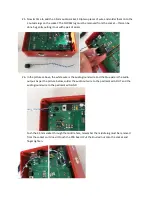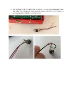
21.
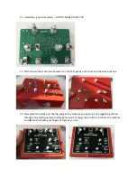
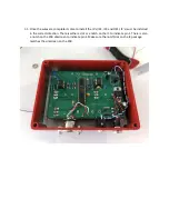
Install the six potentiometers
–
DO NOT SOLDER THEM YET!
22.
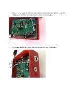
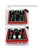
With the switches and potentiometers on the PCB, gently push them into the aluminum box.
23.
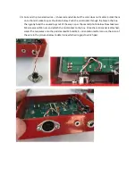
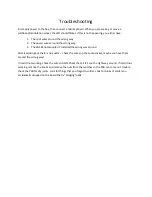
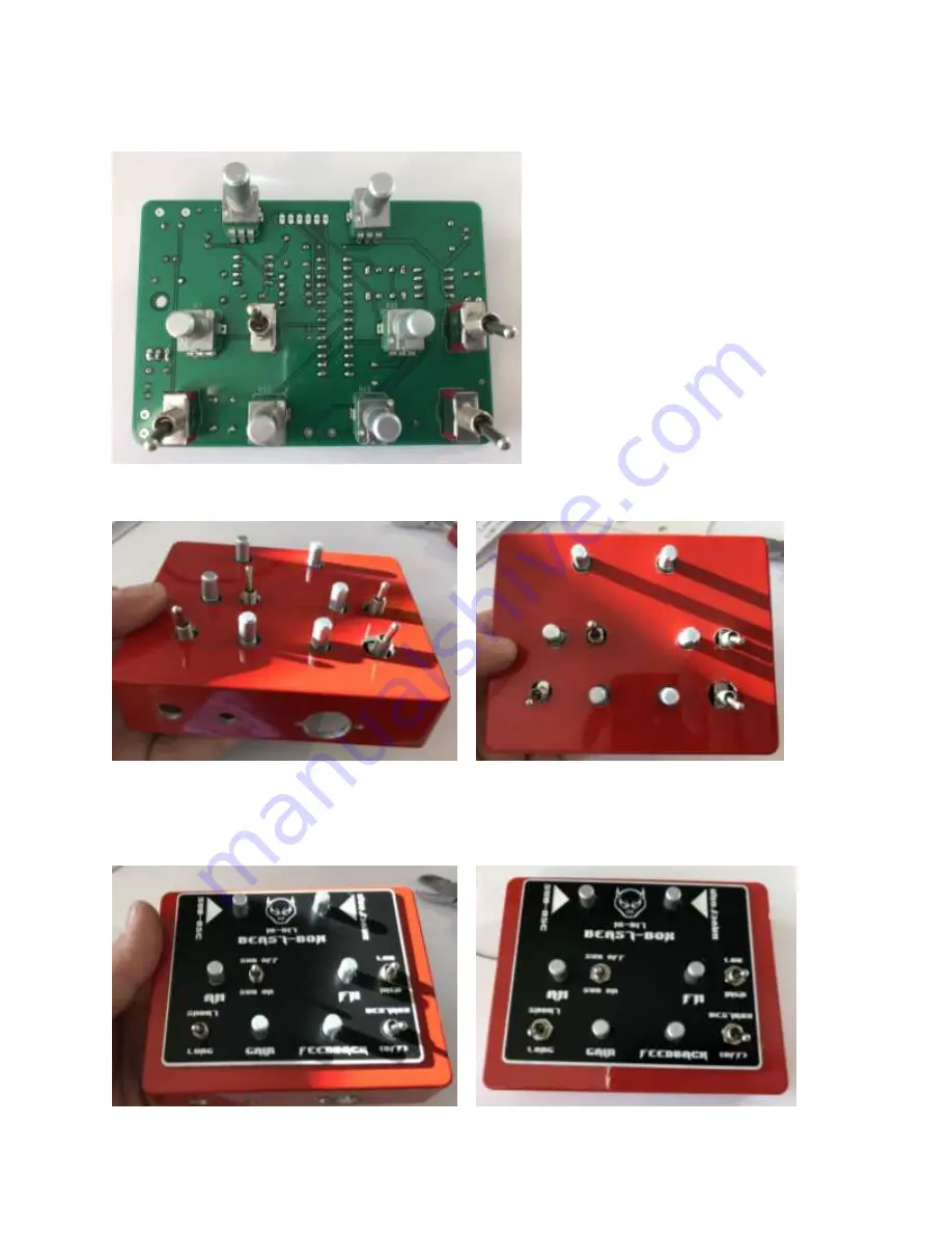
Now place the plastic over the top and give the switches and pots a bit of a wiggle to get them
through and everything seated nicely. When you are happy take 4 of the nuts from the switches
and tighten them with your fingers as tight as you can.
Summary of Contents for BEAST BOX 1.0
Page 1: ...BEAST BOX 1 0 BUILD GUIDE ...
Page 6: ...4 Install IC1 the LD1117v33 voltage regulator and solder into place ...
Page 7: ...5 Install the seven 10K resistors R18 R23 R24 R25 R26 R27 and R30 and solder into place ...
Page 8: ...6 Install L1 the 100uh inductor and solder into place ...
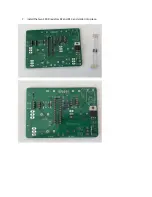
Page 9: ...7 Install the two 100R resistors R2 and R13 and solder into place ...
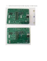
Page 10: ...8 Install the 100K resistor R3 brown black black orange brown and solder into place ...
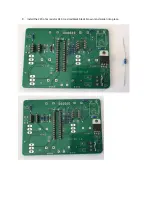
Page 11: ...9 Install the 220 ohm resistor R10 red red black black brown and solder into place ...
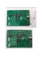
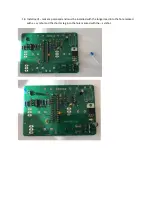
Page 12: ...10 Install the 4 7K resistor R11 yellow violet black brown brown and solder into place ...
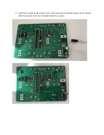
Page 13: ...11 Install the 1K resistor R12 brown black black brown brown and solder into place ...
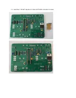
Page 16: ...14 Install the 82nf MKT capacitor C1 marked 823K100 and solder into place ...
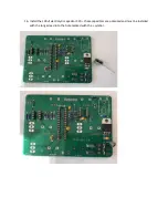
Page 17: ...15 Install the 2 7nf MKT capacitor C3 marked 272K100 and solder into place ...
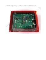
Page 24: ...24 Gently flip the box back over and solder the switches and potentiometers into place ...

