25.
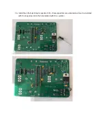
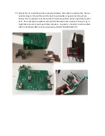
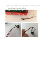
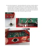
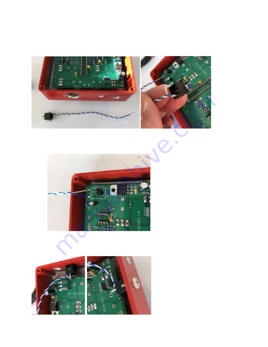
Now its time to add the 3.5mm audio socket. Strip two pieces of wire and solder them onto the
2 outside lugs on the socket. The MIDDLE lug must be removed from the socket
–
this can be
done by gently pulling it out with a pair of pliers.
26.
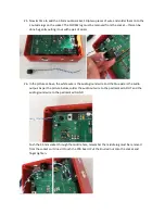
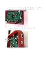
In the pictures above, the white wire is the audio ground wire and the blue wire is the audio
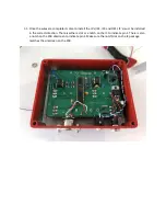
output. As per the picture below, solder the audio out wire to the pad marked A.OUT and the
audio ground wire to the pad marked A.GND.
Push the 3.5mm socket through the middle hole, remember the middle lug must be removed
fro
m the socket so it doesn’t touch the PCB board. Put the knurled nut onto the socket and
finger tighten.
Summary of Contents for BEAST BOX 1.0
Page 1: ...BEAST BOX 1 0 BUILD GUIDE ...
Page 6: ...4 Install IC1 the LD1117v33 voltage regulator and solder into place ...
Page 7: ...5 Install the seven 10K resistors R18 R23 R24 R25 R26 R27 and R30 and solder into place ...
Page 8: ...6 Install L1 the 100uh inductor and solder into place ...
Page 9: ...7 Install the two 100R resistors R2 and R13 and solder into place ...
Page 10: ...8 Install the 100K resistor R3 brown black black orange brown and solder into place ...
Page 11: ...9 Install the 220 ohm resistor R10 red red black black brown and solder into place ...
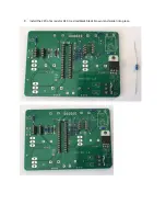
Page 12: ...10 Install the 4 7K resistor R11 yellow violet black brown brown and solder into place ...
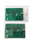
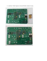
Page 13: ...11 Install the 1K resistor R12 brown black black brown brown and solder into place ...
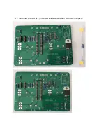
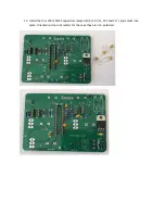
Page 16: ...14 Install the 82nf MKT capacitor C1 marked 823K100 and solder into place ...
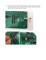
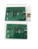
Page 17: ...15 Install the 2 7nf MKT capacitor C3 marked 272K100 and solder into place ...
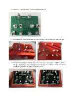
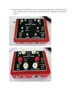
Page 24: ...24 Gently flip the box back over and solder the switches and potentiometers into place ...

