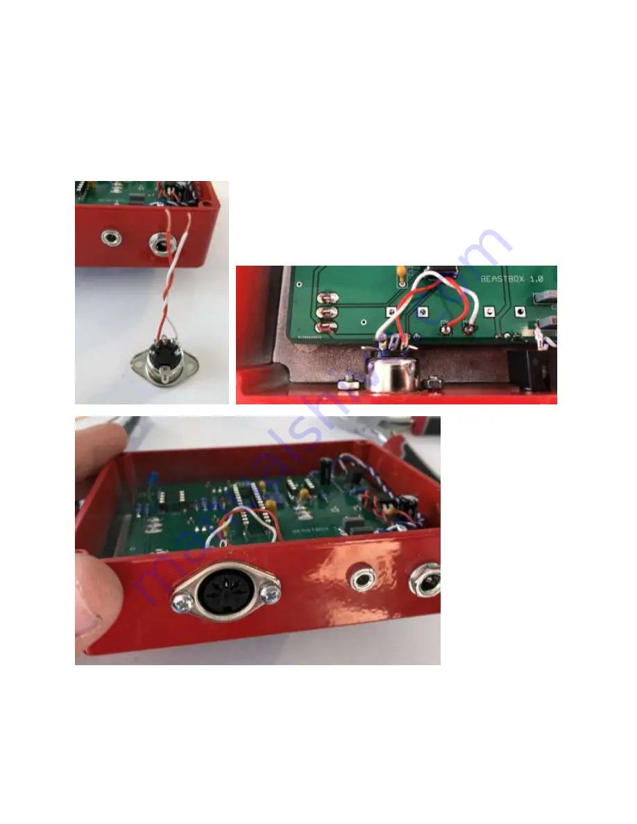
30.
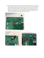
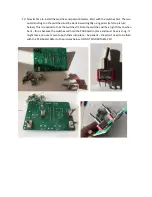
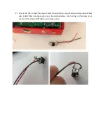
Cut and strip two small wires
–
I chose red and white but the color does not matter. Solder them
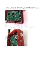
onto the midi socket as per the photo below. Push the midi socket through the hole in the box,
then gently bend the unused lugs out of the way as per the second photo below. Now take two
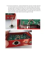
M3 screws and M3 nuts and attach the midi socket to the box. Once the midi socket is attached,
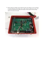
solder the two wires onto the pads marked M5 and M4
–
orientation matters so use the color of
the wire in the pictures below to determine which wire goes to which pad.
Summary of Contents for BEAST BOX 1.0
Page 1: ...BEAST BOX 1 0 BUILD GUIDE ...
Page 6: ...4 Install IC1 the LD1117v33 voltage regulator and solder into place ...
Page 7: ...5 Install the seven 10K resistors R18 R23 R24 R25 R26 R27 and R30 and solder into place ...
Page 8: ...6 Install L1 the 100uh inductor and solder into place ...
Page 9: ...7 Install the two 100R resistors R2 and R13 and solder into place ...
Page 10: ...8 Install the 100K resistor R3 brown black black orange brown and solder into place ...
Page 11: ...9 Install the 220 ohm resistor R10 red red black black brown and solder into place ...
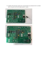
Page 12: ...10 Install the 4 7K resistor R11 yellow violet black brown brown and solder into place ...
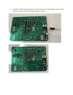
Page 13: ...11 Install the 1K resistor R12 brown black black brown brown and solder into place ...
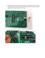
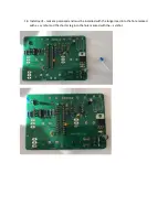
Page 16: ...14 Install the 82nf MKT capacitor C1 marked 823K100 and solder into place ...
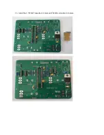
Page 17: ...15 Install the 2 7nf MKT capacitor C3 marked 272K100 and solder into place ...
Page 24: ...24 Gently flip the box back over and solder the switches and potentiometers into place ...

