4
5
85235A
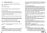
disconnected from the energizer.
The energizer has an AUTO-ON function which ensures that as soon
as power is connected the energizer starts to operate.
Installation with a 230V/110V mains adapter:
For the operation of 230V power supply only use the mains adapter
47PSU0010FEU/FUK,
as specified on the intermediate plate in the device
!
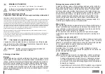
Connect the mains adapter with the energizer, as described in Fig. 3, via the
mains connection
2
. With the mains adapter it is easy to charge a connect-
ed 12 V rechargeable battery in parallel operation.
If the 230 V/110V supply fails, the energizer is then supplied from the re-
chargeable battery.
Installation with 230V/110V:
Insert the energizer’s mains plug into the power socket.
CAUTION!
The energizer has an AUTO-ON function. As such, the energizer
starts following connection to the mains network.
3. Commissioning
Switch on energizer with the push button
1
. After 1 second, you will hear a
rhythmic even ticking of the pulses; the energizer is in operation.
The energizer transmits pulses to the fence and the LED display lights up.
The fact of the status LEDs not lighting up points to a defect in the power
supply.
Commissioning - Power supply units:
Device starts automatically once it is connected to the power supply After 1
second, you will hear a rhythmic even ticking of the pulses; the device is in
operation.
The energizer transmits pulses to the fence and the LED display lights up.
The fact of the status LEDs not lighting up points to a defect in the power
supply
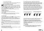
Optimal Solar Alignment and Setting
The correct placement of the pasture fencer and the solar panel is crucial for
the best possible operation of the energizer.
1. Position the pasture fencer so that the panel points south.
This positioning enables the panel to absorb a maximum amount of sunlight
even during the few light winter days When placing the energizer, consider
the position of the sun throughout the day and avoid a location which could
cover the energizer with shade from trees, bushes or high grass.
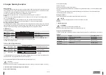
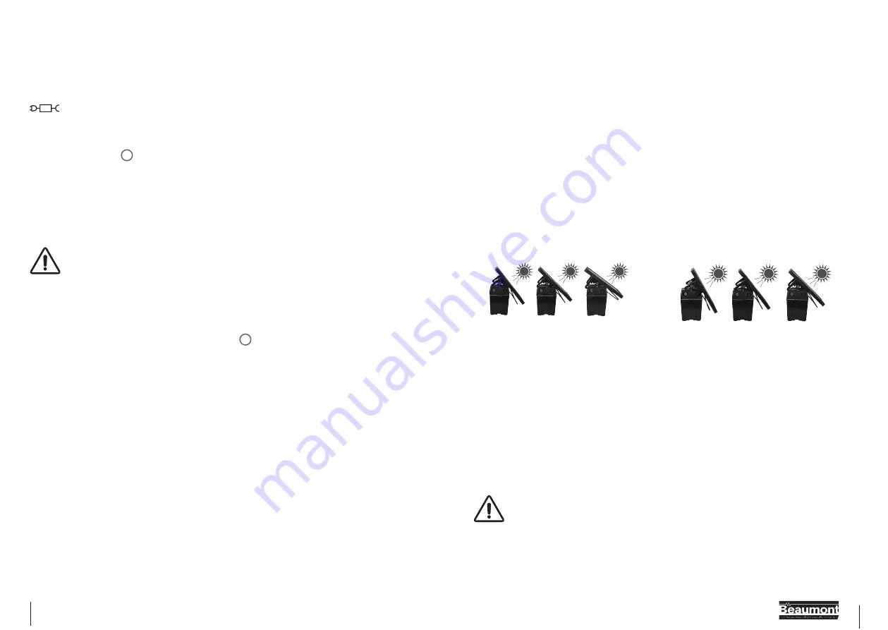
2. Determine the correct angle of inclination for the solar panel.
The position of the sun above the horizon changes during the seasons. As
a general recommendation, an angle of 50 degrees is optimal for long-term
use in most parts of Europe. Nevertheless, the angle can be adjusted condi-
tional upon the season to optimize the output of the solar panel for recharg-
ing the rechargeable battery (see Fig. below). The steeper the angle of
inclination, the greater the cleaning effect during rain or snow.
Recommended setting angle of the panel
South Europe / North Africa (South CH & A)
Winter
Nov. - Feb.
Spring
Mar. & Apr.
Summer
May & Aug.
Fall
Sept. & Oct.
50°
43°
36°
Empfohlener Anstellwinkel des Panels
Nord- & Mitteleuropa (einschließlich A & CH)
Winter
Nov. - Feb.
Frühjahr
Mär. & Apr.
Sommer
Mai & Aug.
Herbst
Sep. & Okt.
60°
50°
43°
It may be the case that in winter (except for southern Europe) there are not
enough hours of sunshine to fully charge the rechargeable battery.
3. Regularly remove any deposits and dirt from the solar panel
This includes removing cut grass, dust (specifically along gravel paths),
leaves and snow, since these can reduce the performance of the module for
recharging the rechargeable battery.
Only check the rechargeable battery indicator in solar operation at dawn
(without sunlight).
WARNING:
Do not leave the switched off pasture fencer in the sun with a re-
chargeable battery and a solar panel for a longer period. Why?
This could damage the rechargeable battery.


