6
7
85235A
4. Energizer Operating Description
Solar operation:
The solar panel produces electricity as soon as it is exposed to usable sunlight. The pasture fencer constantly requires elec-
tricity - by day as well as by night. The electricity generated in this way by the panel is stored in a rechargeable 12V battery,
which means the energizer can operate without sunlight or can be supplied directly by a.
9V battery. The solar panel may not always have a sufficiently large output
to fully recharge a rechargeable battery – especially in dark, grey and misty months (e.g. October to
February).
For temperatures around 0 degrees centigrade or below, we recommend the use of a large 9 V alkaline battery instead
of a 12 V rechargeable battery.
The energizer is operated primarily from the solar panel. If the solar panel does not have sufficient output,
the energizer switches automatically to the connected 9 volt battery or to the 12 volt rechargeable battery.
Rechargeable battery indicator:
The rechargeable battery indicator provides information about the rechargeable battery or battery voltage. The solar display
lights up constantly in green when the solar panel charging voltage is greater than the voltage of the rechargeable battery/
battery. Whilst the solar panel charges the 12V rechargeable battery, it does not charge the 9 volt battery.
5. Maintenance
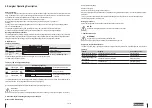
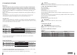
Table 12 (9V battery)
Remaining capacity
Flashing
light
green
15-100%
Battery good
Flashing
light
red/green
5-15
%
Replace battery
Flashing
light
red
5
%
Battery fully depleted
9V battery -
immediately
replace
Replace the battery at the latest when 95% discharged (only 5% charge capacity left).
The battery indicator (LED2) lights up:
Table 13 (12V rechargeable battery)
Remaining capacity
Flashing light green
40-100%
Rechargeable battery good
Flashing light red/
green
20-40%
Charge the battery
Flashing light red
0-20%
Rechargeable battery absolute-
ly depleted
The rechargeable battery must be recharged at the latest when discharged down to 20% (only 80% charge capacity left) to
prevent a flat battery. The rechargeable battery indicator (LED2) lights up:
Do note that temperature and measurement deviation may cause these figures to vary.
Caution!
When using a solar system
Only carry out a battery or rechargeable battery test at start of the day ( no solar power supplied - cover panel )
6. Disassembly, Dismantling, Storage and Transport
Disassembly, Dismantling
Before starting disassembly:
●Switch off energizer
●
Disconnect entire energy supply from the energizer.
●
Remove operating/auxiliary materials and any remaining working materials and dispose of in an environmentally-compati-
ble manner.
Then properly clean sub-assemblies and parts and disassemble them in taking account of the local industrial safety &
environmental protection provisions in force.
Storage, Transport
Ensure that the energizer is both stored and transported only when switched off.
NOTE!
Ensure that rechargeable batteries are stored in ventilated and dry rooms.
7. Faults and Repairs
WARNING!
Repairs may only be carried out by qualified persons.
Only the spare parts prescribed by the manufacturer may be used.
Subject to technical alterations!
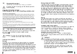
The CONTROL LED (LED1) lights up green when the energizer is working trouble-free. If the LED lights red, there is a fault.
Table 14
Faults
Display
Corrective action
Battery under 15% capacity
LED flashes alternately red/green
Change batteries
Battery under 5% capacity
LED flashes red
Change batteries
Rechargeable battery under
40% capacity
LED flashes alternately red/green
Charge the battery
Rechargeable battery under
20% capacity
LED flashes red
Charge the battery


