1/2019
Installation, Operation, and
Maintenance Instructions
www.beaumontmanufacturing.com
Model LC10 Installation
Installation
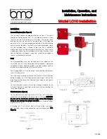
Arm and Displacer (See Figure 1)
The Arm and Displacer are shipped in the box with the LC10 and will
need to be attached before the LC10 is installed into a vessel. Thread
the Arm into the Shaft inside the LC10 Body. This can be done
inserting the Arm into the hole in the end of the LC10 Body and
pushing it in until it can be threaded into the hole in the Shaft located
near the back of the Body. The Shaft may need to be rotated slightly
until the threaded hole is aligned to the front. For a horizontal
arrangement screw the Displacer directly onto the Arm. For a vertical
arrangement, attach the Arm followed by the Swivel Assembly, then
add the Displacer. If vibration is a concern, Loctite can be added to
the Arm threads before installation.
Body
For a threaded Body verify that the condition of the threads on the
vessel and the LC10 are undamaged and free of debris. Apply pipe
compound or Teflon tape to the threads. Insert the Displacer and Arm
into the vessel and thread the LC10 onto the vessel.
For a flanged Body LC10 use the correct Gasket and bolts to connect
the LC10 to the vessel.
For a union connection be sure to put the Hammer Nut over the Body
before threading the LC10 Body into the blind flange. Then put the
blind flange on the end of the Weld Neck and thread on and tighten
the Hammer Nut.
For any installation make sure that there is enough clearance for the
Arm and Displacer to move freely in the vessel without touching the
vessel sides or bottom.
Pilot/Switch (See Figure 3)
Connect low pressure supply gas to the LC10 Pilot. The 1/4 NPT Pilot
connections can be found at the back of the LC10 Case. CAUTION:
Be sure not to exceed the pressure range of the Pilot Gauges.
Doing so can damage the gauges and pilot. The standard Gauges
are 0
-
30 or 0
-
60 psi.
If installing an LC10 with an Electric Switch, follow the proper
electrical codes when making connections and installing conduit. See
Figure 2.
Figure 2
Figure 3
Figure 1

