1/2019
Installation, Operation, and
Maintenance Instructions
www.beaumontmanufacturing.com
Model LC10 Maintenance
Setting the LC10
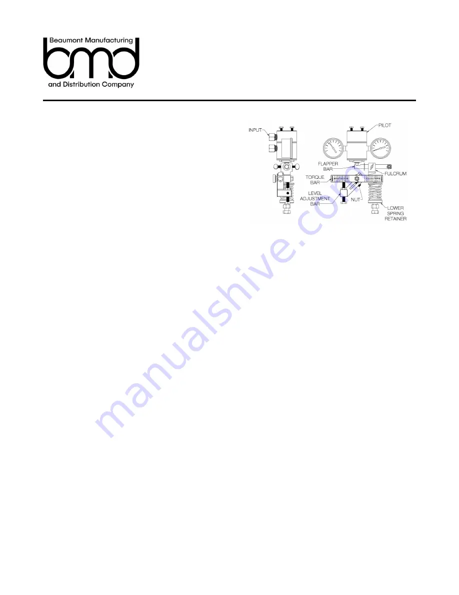
To set the LC10 first connect an airline to the input of the Pilot. Next,
adjust the Lower Spring Retainer so that, when the Arm is in its set
position and then lifted, the Flapper Bar triggers the Pilot.
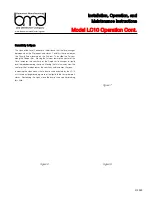
Mounting Change
The LC10 is field reversible which is convenient for arrangement
changes. To switch the LC10 from left to right or vice versa, first
remove the nut holding the Torque Bar and Level Adjustment Bar on
the Shaft. Next, remove the Torque Bar and Level Adjustment Bar.
The Body is held on by two hex head screws. Remove the screws
and rotate the Body to the desired orientation and reinstall the screws
to secure the Body. The Level Adjustment Bar will need to be rotated
clockwise or counter clockwise depending on the initial setup. The
screw will need to be removed from the Level Adjustment Bar and
threaded into the correct hole once the Bar has been rotated. The
Spring, Upper and Lower Spring Retainer, and Screw will swap to the
other side. Put the Level Adjustment Bar and Torque Bar back on the
Shaft and use the nut to secure them. Finally, The Fulcrum Assembly
will need to be moved to the opposite side. Unscrew the nut holding it
on the stud and simply swap to the other side. Reference Figure 11.
Action Change
To change an LC10 from reverse to direct or vice versa simply
unscrew the nut holding on the Flapper Bar. Remove the Flapper Bar
and move it to the other side of the Case. Don’t forget to swap the
Thumb Screw around to the front. Re
-
install the nut taking care not
to over tighten it. Overtightening the nut will hinder the Flapper Bar
from rotating and will cause the unit to malfunction. For best
performance the nut should be snugged up against the Flapper Bar
then backed off about 1/8 of a turn.
Body Maintenance (See Figure 12)
To replace the soft goods in the Body of the LC10 unscrew the nut
holding on the Torque Bar and Level Adjustment Bar, remove them
from the Shaft, and remove the Body from the Case by unscrewing
the two hex head screws. Once the Body is removed, unscrew both
Bearing Blocks to reveal the two O
-
rings and Backup Ring on each
side. Remove the old O
-
rings and Backup Rings and replace them
with the new ones provided in the repair kit. Before installing the new
O
-
rings, grease them with multi
-
purpose synthetic grease for reduced
wear and longer life expectancy. Reinstall the Bearing Blocks into the
Body and attach it back to the Case securely tightening the two hex
head screws. Put the Level Adjustment Bar and Torque Bar back on
the Shaft and secure them with the nut.
Figure 10
Figure 12
Figure 11
Left Hand Reverse
Right Hand Reverse
Left Hand Direct
Right Hand Direct

