background image


IPC@CHIP DB54 

Hardware Manual V1.1 [04.10.2007] 


4. Electrical Functions / Interfaces 

4.1 Power supply 

The 24V power supply input of the DB54 is protected against reverse polarity and transient over-voltages. An 

operating voltage indication (LD1) is located near the power supply socket. Dimming of the power indication LED 

signals reset of the SC23.  

A switching controller from the 9...30V DC power supply of the DB54 is used to provide the internal 3.3V power 

supply. This voltage is also provided at different pin header for external expansions, the 3.3V switching controller 

can supply 600mA for external expansions. In the basic configuration, the maximum internal load of the 3.3V 

power supply is 400mA. An additional switching controller provides 5V/500mA from the 24V operating voltage of 

the DB54 for the USB host function. 


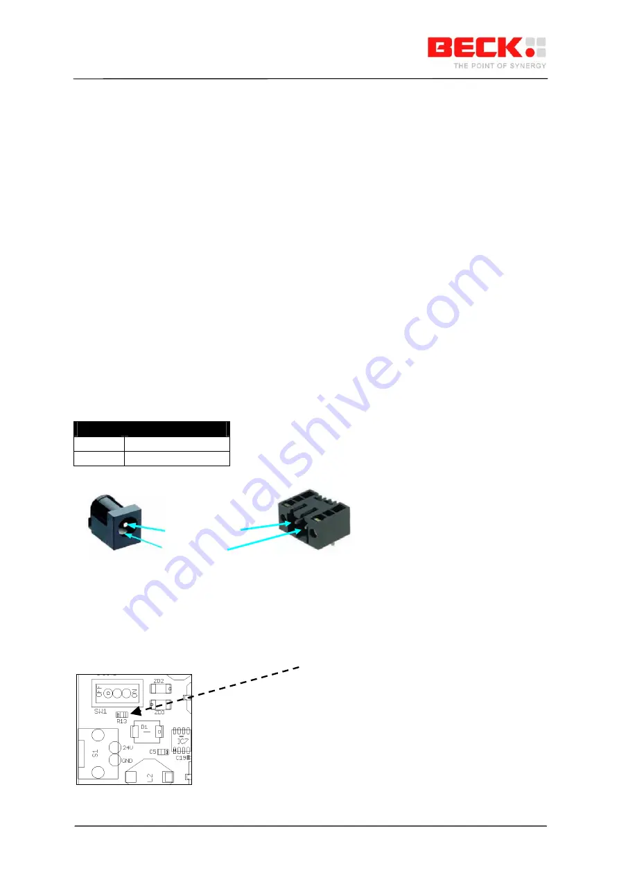
4.2 ST12 & S1 - Power supply connector  

Power supply connectors for the DB54  

Pin assignment: 


Pin No. 

Designation

1 (pin) 

24V DC  (9..30V DC) 

2 (shield) 

GND 


4.3 SW1 - 24V switch  

Switch for the operating voltage of the DB54 

Not assembled / optional assignment: e.g. APEM 25136NAH silver ON-ON 

If the switch is to be assembled later, the 0 Ohm R13 resistor near the SW1must be removed.


Top view 


   9..30V DC (pin) 

d) 

GND (shiel

©2000-2008 Beck IPC GmbH 


Page 7 of 24 

Summary of Contents for IPC@CHIP DB54

Page 1: ...V1 1 04 10 2007 Hardware Manual IPC CHIP Development Board DB54 High Performance IPC CHIP SC23 Embedded Web Controller Order No IPC CHIP Development Board DB54 Development Kit DK55 553946 553947 2000 2008 Beck IPC GmbH Page 1 of 24 ...

Page 2: ...tered trademark of Xerox Corporation SPI is a trademark of Motorola Inc No part of this guide may be reproduced or transmitted in any form for any purpose whatsoever other than the purchaser s personal use without the express written permission of Beck IPC Beck IPC GmbH Grüninger Weg 24 35415 Pohlheim Garbenteich Germany Phone 49 6404 695 0 Fax 49 6404 695 500 Technical Support Phone 49 6404 695 2...

Page 3: ...S31 S32 WLAN SUPPORTING PIN HEADERS 11 4 12 S30 I2C INTERFACE 13 4 13 ST15 RS232 INTERFACE COM1 13 4 14 S41 JUMPER ARRAY COM1 14 4 15 ST14 RS232 INTERFACE COM2 15 4 16 S40 JUMPER ARRAY COM2 15 4 17 S42 DCD DTR DSR CONNECTOR 16 4 18 S32 SERIAL INTERFACE COM3 SPI 16 4 19 ST1 SD MMC INTERFACE 17 4 20 ST4 PIO JUMPER ARRAY 17 4 21 ST3 ETHERNET INTERFACE 18 4 22 S6 CAN0 INTERFACE 18 4 23 S38 CAN1 COM2 I...

Page 4: ...e I C bus and SPI Serial Peripheral Interface The USB interface supports user specific connections to standard USB hosts like PCs USB device mode or memory expansion with USB sticks USB host mode The DB54 development board is designed to provide an easy introduction to the SC23 technology both for software development in C C and in IEC61131 It also provides a hardware basis for quickly developing ...

Page 5: ...A DC Connector DC Converter RS232 LED GPIO TTL RS232 USB B TTL ETH0 100 10 Base T Reset Button TTL IPC CHIP DC Converter CAN Bus USB A pinheader jumper I2C Bus RS232 I2C GPIO DSUB male COM1 Serial RS232 Interface DB54 features are Embedded Web Controller SC23 9 30V power supply input protected against reverse polarity Power LED 3 3V and 5V power supply Reset button Power fail button for power fail...

Page 6: ...IPC CHIP DB54 Hardware Manual V1 1 04 10 2007 3 Component layout diagram 2000 2008 Beck IPC GmbH Page 6 of 24 ...

Page 7: ...l expansions the 3 3V switching controller can supply 600mA for external expansions In the basic configuration the maximum internal load of the 3 3V power supply is 400mA An additional switching controller provides 5V 500mA from the 24V operating voltage of the DB54 for the USB host function 4 2 ST12 S1 Power supply connector Power supply connectors for the DB54 Pin assignment Pin No Designation 1...

Page 8: ... digital input and output simulation The DIP switch is connected to an I2C I O port expander PCF8574A It is coded to the I2C base address 72hex A switch in the ON position will read out logic 0 and a switch in the OFF position will read out logic 1 Using the I2C port expander it ispossible to have a practical expansion of input and output signals for the SC23 switch PCF8574A I O expander BIT7 D7 B...

Page 9: ...es the 4 bit mode The I2C address of the LCD interface is 74hex Sample programs for handling the LCD can be obtained from the BECK IPC website Pin assignment Display pins Board Pin Display Pin Name 1 14 D7 2 16 D6 3 1 D5 4 2 D4 5 3 D3 6 4 D2 7 5 D1 8 6 D0 9 7 E 10 8 R W 11 9 RS 12 10 VEE 13 11 VDD 14 12 GND 15 13 LCD_LED_K 16 15 LCD_LED_A Signal descriptions of the asynchronous serial interface Si...

Page 10: ...ption 1 24V 9 30V DC DB54 board power supply 2 GND 3 5V 5V power supply for USB host CAN 4 VCC_USB_DEVICE Voltage input of USB Device Interface 5 3 3V 3 3V logic voltage 6 GND 4 9 IC11 IPC CHIP SC23 Socket Socket for the IPC CHIP SC23 module The SC23 is described in the SC2x Hardware Manual Pin assignment 32 pin IC socket Pin No Name Description Pin No 1 RXD1 PFI PIO9 32 2 TXD1 TMRIN1 INT5 PIO0 31...

Page 11: ... 7 CTS2 CAN1RX PIO12 RESETOUT 28 8 RTS2 CAN1TX PIO20 I2CCLK PIO31 27 9 RXD3 SDI PIO28 I2CSDA PIO13 26 10 TXD3 SDO PIO27 CAN0RX 25 11 RTS3 SCK PIO19 CAN0TX 24 12 CTS3 SEL PIO18 NC 23 13 USBP NC 22 14 USBN NC 21 15 3V3 NC 20 16 GND RESETIN TRAFFIC 19 17 NC NC 18 4 11 S9 S31 S32 WLAN supporting pin headers The S9 pin header in conjunction with S31 and S32 supports the usability of the FK61 WL01 WLAN ...

Page 12: ...C 22 23 NC NC 24 25 NC NC 26 27 NC NC 28 29 NC NC 30 31 NC NC 32 33 NC NC 34 35 WLAN_SEL NC 36 37 WLAN_RES NC 38 39 NC NC 40 Signal descriptions of the expansion interface Signal name Direction Description WLAN_INT Input INT5 PIO0 TMRIN1 WLAN_SEL Output PIO12 CTS1 WLAN_RES Output PIO2 INT1 WLAN SPI Connector Pin assignment 1x6 pin header pitch 2 54mm Pin No Name 1 VCC 2 GND 3 SDO TXD3 PIO27 4 SDI ...

Page 13: ... SPI clock VCC 3 3 power supply e g for externally connected level converter GND GND Signal reference 4 12 S30 I2C Interface Alternatively PIO signals can also be configured on the signals of the I2C interface 1 K Ohm pull up resistors are connected on SDA and SCL Pin assignment pin header pitch 2 54mm Pin No Name 1 VCC 2 GND 3 I2CSDA P13 4 I2CCLK P31 5 NC 6 NC Signal descriptions of the I2C inter...

Page 14: ... line RS232 V24 level CTS1 Input Handshake line Clear To Send RS232 V24 level RTS1 Output Handshake line Request To Send RS232 V24 level GND GND Signal reference 4 14 S41 Jumper array COM1 A jumper placed at this pin header allows the serial interfaces of the SC23 to be used with an RS232 level Removing the jumpers allows the serial signals to be used directly as TTL levels e g for RS485 driver Pi...

Page 15: ...V24 level CTS2 Input Handshake line Clear To Send RS232 V24 level RTS2 Output Handshake line Request To Send RS232 V24 level DCD No function connected to S42 DTR No function connected to S42 DSR No function connected to S42 GND GND Signal reference 4 16 S40 Jumper array COM2 This jumper array allows the serial interfaces of the SC23 to be used with an RS232 level Removing the jumpers allows the se...

Page 16: ...pull up resistors at SDO and SDI enable the SPI interface to run in slave mode Pin assignment 1x3 pin header pitch 2 54mm Pin No Name 1 VCC 2 GND 3 TXD3 SDO P27 4 RXD3 SDI P28 5 CTS3 SEL P18 6 RTS3 SCK P19 Signal descriptions Signal name Direction Description TXD3 P27 SDO Output Bi directional Output Serial data Transmit line TTL level PIO27 SDO serial data out SC23 as SPI master MOSI SC23 as SPI ...

Page 17: ... PIO27 3 GND 4 3 3V 5 SCK RTS3 PIO19 6 GND 7 SDI RXD3 PIO28 8 GND 9 NC 10 WP PIO10 11 CD PIO11 12 COMMON GND 13 GND shield 14 NC Signal descriptions of the SD MMC interface Signal name Direction Description SDO Output Serial synchronous data output SDI Input Serial synchronous data input SLVSEL Output SPI Slave Select SCK Output SPI clock CD PIO11 Input Card Detect 0 Card present 1 Card not presen...

Page 18: ...utput Differential 10 100 Base T transmit signal from SC23 TPTX Output Differential 10 100 Base T transmit signal from SC23 TPRX Input Differential 10 100 Base T receive signal from SC23 TPRX Input Differential 10 100 Base T receive signal from SC23 Ethernet Jack with integrated LED s RJ45 Ethernet Jack LED Description green LED right side TMROUT0 PIO1 Activity Status orange LED left side On activ...

Page 19: ...iver Alternatively the signal lines of the CAN1 interface can also be used as PIO functions The CAN1TX and CAN1RX signals are shared with the signals RTS2 and CTS2 Pin assignment pin header 6 pole pitch 2 54mm Pin No Name 1 VCC 2 GND 3 CAN1T CTS2 PIO20 4 CAN1R RTS2 PIO21 5 NC 6 5V Signal descriptions of the CAN interface Signal name Direction Description CAN_TXD PIO20 CTS2 Bi directional Bi direct...

Page 20: ...D VCC CAN_SHLD 1 7 4 6 5 8 2 VCC Example of the CAN interface without galvanic isolation IC1 SN65HVD231 1 4 5 8 6 7 2 3 TXD RXD REF RS CANL CANH GND VCC CANH 3V3 GND C2 10uF CANTX CAN CANRX CANL P2 D SUB 9f 5 9 4 8 3 7 2 6 1 NC 5V CAN1 S38 1 2 3 4 5 6 C1 100uF CAN_GND GND 4 24 ST16 ST13 USB Interface The USB interface of the DB54 has the ability to work in host or device mode A software driver is ...

Page 21: ... reference The external USB voltage can be taken from pin header S39 pin 4 ST13 USB device pin assignment USB B mini connector Pin No Name 1 VCC_USB_DEVICE connected to S39 pin 4 2 USBN 3 USBP 4 AB_DETECTION 5 GND Signal descriptions of the USB device interface Signal name Direction Description USBN Bi directional Differential USB signal USBP Bi directional Differential USB signal AB_DETECTION Not...

Page 22: ...ient temperatures 0 55 C 5 2 Mechanical data DB54 board module dimensions H x L x D 31mm x 135mm x 195mm 1 mm 5 3 Electromagnetic data This product is a development board without the CE mark 5 4 Electrical data Input voltage 9 30 VDC Current consumption DB54 without expansions max 1 7 W 2000 2008 Beck IPC GmbH Page 22 of 24 ...

Page 23: ... be used for hardware software development Use of the development board outside the specified environment is the responsibility of the user and shall be carried out at his or her own risk exempting Beck from any liability Claims by the user for compensation against Beck in conjunction with the use of this product shall be excluded Insofar that information hardware software and documentation is tra...

Page 24: ...that may appear in this document BECK IPC GmbH makes no commitment to update or keep current the information contained in this document Life critical applications BECK products are not authorised for use as critical components in life support devices or systems unless a specific written agreement pertaining to such intended use is executed between the customer and BECK prior to use Life support de...

Reviews: