12
Assembly and Operating Instructions
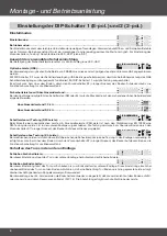
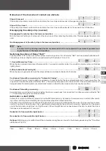
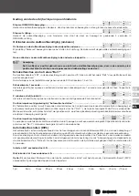
Setting DIP Switches 1 (8pole) and 2 (2pole)
Setting mode
Setting mode: ............................................................................................
1
2
3
4
5
6
7
8
ON
OFF
DIP
1
1
2
ON
OFF
DIP
2
Operating mode: ........................................................................................
1
2
3
4
5
6
7
8
ON
OFF
DIP
1
1
2
ON
OFF
DIP
2
The setting mode allows the relevant door end positions to be set. Here the open and close commands are only executed in
deadman mode, allowing “tapping” to the desired position.
To set the “Testing” prelimit switch watch the “VES” LED (see p. 15).
Selection of Protective System Used
When the safety edge is actuated the green bottom rail deactivation LED lights up as a signal.
Optical Safety Edge (OSE): ...........................................................................
If the FRABA optical safety edge is used, it must be connected up to the OSE 3pin plugin terminal.
With DIP switch 2.2 the safety edge input for bottom rail deactivation must be switched off so that the selfmonitoring system
of the OSE safety edge input operates properly. With DIP switch 1.1 testing is switched off. Function shutdown for the return
journey upwards is performed at a maximum of 5 cm above the floor, by prelimit switch S7 (orange cam) of the BECKER
direct mount drive.
Safety Edges with Terminating Resistor: ...........................................................
1
2
3
4
5
6
7
8
ON
OFF
DIP
1
1
2
ON
OFF
DIP
2
If either of the safety edges DW or EL is used, the plugin card must be set to the terminating resistor fitted.
1.2 k
Ω
terminating resistor: ..................................................................
1
2
3
4
5
6
7
8
ON
OFF
DIP
1
1
2
ON
OFF
DIP
2
8.2 k
Ω
terminating resistor: ..................................................................
1
2
3
4
5
6
7
8
ON
OFF
DIP
1
1
2
ON
OFF
DIP
2
Safety Edges with Testing (DW Edge): ..............................................................
If a pneumatic safety edge is used, i.e. pressure wave safety edge (DW edge) a pressure wave test is obligatory according
to the specifications of EN 12453, e.g. at the bottom end limit. The test is started at a maximum of 5 cm above the floor by
prelimit switch S7 (orange cam) of the Becker direct mount drive.
Safety Edges without Testing (EL Edge): ...........................................................
In the case of electric safety edges no test is required at the end limits because of the selfmonitoring closedcircuit pro-
tection. However, function shutdown for the return journey upwards is performed at a maximum of 5 cm above the floor, by
prelimit switch S7 (orange cam) of the Becker direct mount drive.
Behaviour of the door in the lower end position
Closing as far as the connecting block: ............................................................
1
2
3
4
5
6
7
8
ON
OFF
DIP
1
1
2
ON
OFF
DIP
2
With this setting the door stops in the lower end position when it touches the safety strip.
Closing as far as the limit switch: ....................................................................
1
2
3
4
5
6
7
8
ON
OFF
DIP
1
1
2
ON
OFF
DIP
2
With this setting the door closes as far as the lower end position limit switch. Where the ground is uneven, this setting allows
the door to contact the ground in such a way as to enable door/ground sealing by means of the pressed strip.
Use a double chamber profile here if possible!
If an EL safety edge is used, the limit switches are set either so that the edge is not resting on the floor or the edge is relieved
by reversing (DIP 1.4). The edge is sealed home by the sealing lip on the safety edge.


