
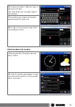


3
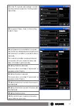
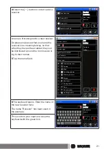
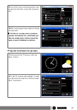
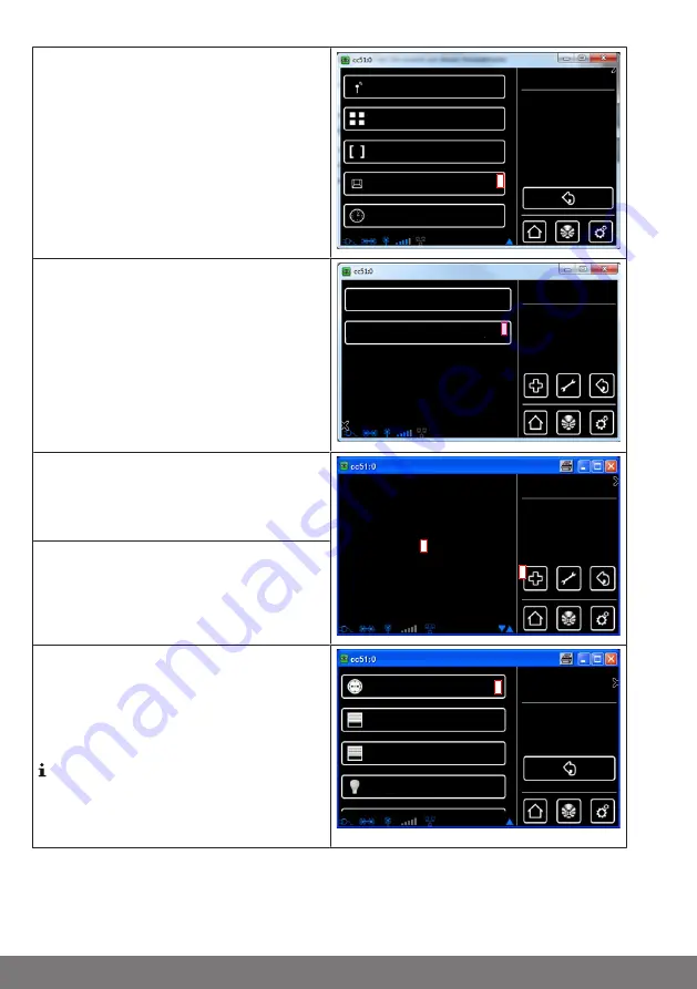
On the "House installation" screen you
should now select the "Rooms" menu
item.
Rooms
Scenarios
Groups
Setup
Receiver
Please select
a function
3
Timers
4
Choose the room in which you want to
add receivers.
For example: Bedroom
Rooms
Add / select
room
Living room
4
Bedroom
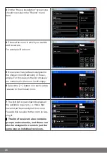
5
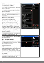
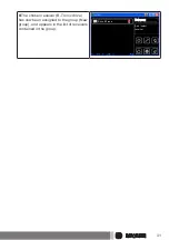
No receiver has yet been assigned to
the chosen room (Bedroom) in the ex-
ample. For this reason, the list of receiv-
ers contained in the room is still empty.
Bedroom
Add / select
receiver
or edit room
5
6
6
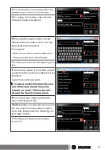
Select the [ + ] button in order to add a
receiver to the chosen room.
7
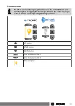
The list that is now shown displays all
the available receivers, i.e. those that
have not yet been assigned to a room.
You add this receiver to the room by tap-
ping it.
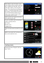
The list of receivers also contains
groups and scenarios, and these can
also be assigned to rooms in just the
same way as individual receivers.
Add
receiver
Choose a
receiver to add
Switch
Drives
Drive Centronic
Dimmer KNX
7
26


