background image

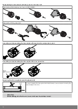
Disassembling the plug-in connecting cable for tubular drives dia. 45 and dia. 58

Caution

Prior to disassembly, the power supply to the connecting cable must be disconnected.

Insert a suitable flathead screwdriver right into the recess of the locating latch, so that the latch releases the locating lug from the
plug.

Now you can pull out the connecting cable along with the flathead screwdriver.

dia. 45 and dia. 58

1.

2.

A

A = locating latch

8

Summary of Contents for M04

Page 1: ... drives with mechanical limit switch Important information for Fitters Electricians Users Please forward accordingly These instructions must be kept safe for future reference Becker Antriebe GmbH Friedrich Ebert Straße 2 4 35764 Sinn Germany www becker antriebe com 2010 300 332 0h 07 09 2016 ...

Page 2: ... 9 Assembling the drive adapter with safety catch on the drive shaft 9 Disassembling the drive adapter with safety catch on the drive shaft 10 Assembling and disassembling the drive adapter with separate drive adapter safety catch 10 Assembling and disassembling the drive adapter with screw connection 10 Securing the drive against axial displacement 10 Fixing the drive adapter to the barrel dia 35...

Page 3: ...result in injury ATTENTION ATTENTION indicates measures that must be taken to avoid damage to property Denotes user tips and other useful information Warranty Structural modifications and incorrect installation which are not in accordance with these and our other instructions can result in serious injuries e g crushing of limbs Therefore structural modifications may only be carried out with our pr...

Page 4: ...nstructions in EN 60335 2 97 Please note that this list of safety instructions is not exhaustive since it would be impossible for the standard to include all sources of danger For example the design of the operated product the way the drive works in the situation it is installed in or even the way the end product is mounted in the end user s place of use cannot be taken into consideration by the d...

Page 5: ...its are operated certain components e g the power supply unit are live Physical injuries or damage to property can result in the event of unauthorised interventions or failure to heed warnings Be careful when touching the tubular drive as it heats up during operation for technolo gical reasons Before installation shut down all lines and control devices that are not essential for op eration Crushin...

Page 6: ...rmitted in order to protect the safety of the users and others since these ac tions can impair the system s safety and carry the risk of personal injury and property damage The drive manufacturer does not accept liability for damages or injury arising from such actions Always observe the information in these instructions when operating or repairing the system The drive manufacturer does not ac cep...

Page 7: ...wer supply to the connecting cable must be disconnected Insert a suitable flathead screwdriver between the locating lug and the snap in pin so that the snap in pin releases the locating lug from the plug Now you can pull out the connecting cable along with the flathead screwdriver dia 35 A A snap in pin 7 ...

Page 8: ...wer supply to the connecting cable must be disconnected Insert a suitable flathead screwdriver right into the recess of the locating latch so that the latch releases the locating lug from the plug Now you can pull out the connecting cable along with the flathead screwdriver dia 45 and dia 58 1 2 A A locating latch 8 ...

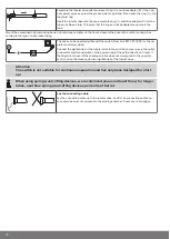
Page 9: ...ed at the side M and idler G gives the length L of the barrel L X M G The space required at the side M varies depending on the combination of drive and wall bracket Then mount the wall bracket and idler Ensure that the barrel is aligned at right angles to the wall and that sufficient axial play is al lowed for the mounted system Attention When using rigid shaft connectors closed brackets must be f...

Page 10: ... disassembling the drive adapter with separate drive adapter safety catch Assembling and disassembling the drive adapter with screw connection Securing the drive against axial displacement 10 mm In order to secure the drive against axial displacement we recommend screwing the drive adapter to the tube Attention When drilling into the barrel never drill near the tubular drive 10 ...

Page 11: ... 58 63 120 mm diecast drive adapter 120 Self tapping screw dia 6 3 x 13 mm We also recommend screwing the idler to the barrel Attention Do not hammer the tubular drive into the tube or drop it into the barrel The curtain can only be secured using springs or rigid shaft connectors Mounting the drive in the tube For profile tubes In the case of some drive adapters tolerances of the groove widths in ...

Page 12: ... 0 or the op erator control provided Connect the pigtail wires of the tubular drive to those of the same colour in the switch or operator control and switch on the power supply Check the direction of travel If the direction of travel of the shading solution does not correspond to the operator control swap the black and brown pigtail wires of the tubular drive Attention The switch is not suitable f...

Page 13: ...ch anical stops Make sure that the individual laths cannot shift sideways During commissioning and subsequent use ensure that the roller shutter curtain runs UP and DOWN smoothly and easily Test for proper functioning As a final check run the shading solution to the limit positions in both directions again Attention The tubular drives are designed for short time operation for the operating mode pl...

Page 14: ...not execute simultaneous UP and DOWN com mands Protect the electrical connections from damp Once you have finished wiring everything to the control ALWAYS check the right direction assignment of the drive to the control buttons UP and DOWN EXTEND and RETRACT If the drive is to be operated with devices which contain sources of interference the elec trician must ensure suitable interference suppress...

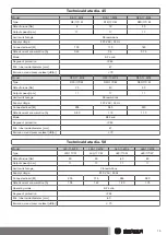
Page 15: ... rpm 17 17 11 Limit switch range 38 revolutions Supply voltage 230 V AC 50 Hz Connected load W 205 260 240 Rated current consumption A 0 90 1 15 1 10 Mode S2 4 min Degree of protection IP 44 Min tube inside diameter mm 47 Emission sound pressure level dB A 70 Technical data dia 58 Model L50 11 M04 L50 17 M04 L60 11 M04 L60 17 M04 Type L50 11C M L50 17C M L60 11C M L60 17C M Rated torque Nm 50 50 6...

Page 16: ...nside diameter mm 60 Emission sound pressure level dB A 70 This tubular drive is not yet available What to do if Problem Cause Remedy The roller shutter curtain is raised un evenly or not at all 1 One or more attachments have broken off 2 Lath has broken off Repair system then reset the limit posi tions Tubular drive stops arbitrarily cannot be restarted in the same direction Roller shutter curtai...

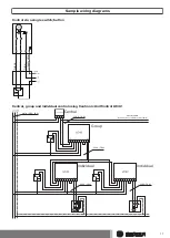
Page 17: ...n blue green yellow Central group and individual control using Centronic UnitControl UC42 Mains 230 V 50 Hz Central Group Individual Individual 230 V 50 Hz Central cable connection to further control units 230 V 50 Hz 230 V 50 Hz Electronics 230 V 50 Hz Control unit 17 ...

Page 18: ...Declaration of conformity 18 ...

Page 19: ...19 ...

Page 20: ......

Reviews: