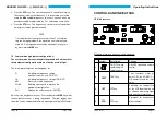
The back side of the unit contains:
·
the BNC-antenna jacks for the VOR/LOC-receiver
·
the TNC-antenna jacks for the GS-receiver
·
the 15-pole D-sub connector plug (female) for the outputs of the
VOR/LOC converter board (NR 3320 - ( 01) and NR 3330 -(01)
only)
·
the 9-pole D-sub connector plug (female) for the I/O Outputs of
the RS 422 interface.
·
the 25-pole D-sub connector plug (male) unit connector plug
The electronic elements of the unit are distributed among the following
boards, which are linked with one another by means of p.c. connectors:
1. Chassis board
2. VOR/LOC receiver board
3. VOR/LOC converter board
4. GS receiver board
5. Processor board
6. Display board
7. Interface board
The interface board and the processor board are mounted and fastened
by means of four screws on the frame of the control head. The display
board with the two liquid crystal displays is located between the front
plate and the panel.
BECKER NR 3320 - ( ) / NR 3330 - ( )
Page 8
Issue 12/97
Entry of password to interlock the equipment configuration
Call up the “COdE” function using the
MDE
key. The following display
appears:
left LC-Display
COdE
right LC-Display
0000
Set any 4-digit numerical code. Using the
MHz
frequency selector
switch, select the character (two digit left) and
kHz
frequency selector
switch, select the character (two digit right) . Store the numerical code
by pressing the
STO
key.
NOTE
As soon as a password is given a “0000" appears in the right
LC-Display when the service mode is called up. The numeri-
cal code must then be input using the
MHz
and
kHz
frequen-
cy selector switch and press the
STO
key. If the navigation
receiver detects a false numerical code, it automatically swit-
ches to the last mode. If the password is to be erased or chan-
ged, this is done by calling up the service mode using the old
password. The COdE function is then chosen and either a
”0000" is entered everywhere or the changed numerical code
is entered.
Operating Instructions
Issue 12/97
Page 25

