background image

q

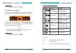
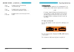
TEST mode (by pressing the TEST button)

Press the TEST key. All digits should flash on and off in both liquid crys-
tal displays (display test). At the same time, the VOR/LOC pointer (verti-
cal needle) of the connected indicator should deflect fully and the
VOR/LOC warning flag should disappear from view. In the NAV re-
ceiver NR 3320 - (1) the GS pointer (horizontal needle) of the connected
indicator should deflect fully and the GS flag should disappear from
view.

q

VOR mode

1. Set the frequency of the wanted VOR station.

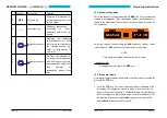
2. To monitor the identification signal, press the

IDT

key (ON appe-

ars briefly in the (right indication) of the LC display). Monitor the
identification signal and compare it with the identification signal of
the wanted VOR station. Adjust the volume using the

VOL

control.

3. If an evaluable VOR signal enables a safe bearing to be establis-

hed, the vertical needle deflects and the VOR/LOC flag disappe-
ars from the field of view.

4. Rotate the omnibearing selector (

OBS

) on the display unit until

the TO/FROM display indicates TO and the vertical needle has
settled in the mid position. The heading indication then indicates
the magnetic course to the VOR station.

5. Course deviations during the approach are indicated in the directi-

on of correction by the vertical needle (course correction in the di-
rection of the needle deflection).

BECKER NR 3320 - ( ) / NR 3330 - ( )

Page 16

Issue 12/97

6. When overflying the VOR station, the TO/FROM display moves

from TO to FROM. If the flight is continued on the same heading,
the course indication shows the magnetic position line of the VOR
station which the aircraft is approaching, with the vertical needle
in the mid position.

q

Monitoring flight and weather information

1. Press the

IDT

key. The word OFF appears briefly in the (right indi-

cation) of the LC display. Identification transmissions are faded
out.

2. The fading out of the VOR/LOC indentification signal means that

flight and weather information can now be monitored.

3. Press the

IDT

key again. The word ON appears briefly in the dis-

play. The identification signal can now be monitored.

q

LOC mode

1. Set the frequency of the required localizer.

2. Switch on the VOR/LOC identification (press the

IDT

key, ON ap-

pears briefly in the display). Monitor the Morse identification signal
and compare it with the identification signal of the wanted locali-
zer.

3. The vertical needle (command needle) deflects during the appro-

ach to the localizer in the direction in which the course is to be
corrected in order to obtain the correct landing course. A mid posi-
tion of the needle means that the aircraft is on the correct line for
landing.

Operating Instructions

Issue 12/97

Page 17

Summary of Contents for NR 3320

Page 1: ...cal changes OPERATING INSTRUCTIONS Navigation Receiver NR 3320 01 02 NR 3330 01 02 BECKER FLUGFUNKWERK GMBH Baden Airpark B 108 D 77836 Rheinm nster Germany Tel 49 0 7229 305 0 Telex 781 271 beflu Fax...

Page 2: ...ure Should the fault only occur sporadically please answer the following questions The fault occurs after minutes of operation The fault occurs under the following environmental conditions p low tempe...

Page 3: ...71 BECKER NR 3320 NR 3330 Page 32 Issue 12 97 TABLE OF CONTENTS Page IMPORTANT 1 INTRODUCTION 1 SAFETY PRECAUTIONS 3 GENERAL INFORMATION 5 p Short description of NAV receiver 5 CONTROL AND INDICATORS...

Page 4: ...needles and or flags with 1 kW each GS warning flag output max of 3 needles and or flags with 1 kW each q Indicators VOR LOC indicator singlepointer IN 3300 4 9 or for NR 3330 01 equivalent indicator...

Page 5: ...ssue 12 97 IMPORTANT Carefully read these operating instructions right through before attemp ting to operate the NAV receiver Keep these operating instructions carefully They contain important sa fety...

Page 6: ...be low 55 C or above 85 C is to be avoided l Switch off the unit when starting or shutting down engines BECKER NR 3320 NR 3330 Page 4 Issue 12 97 WARNING CAUTION CAUTION AGC 3 dB from 87 dBm 10 dBm Di...

Page 7: ...unit appears the course de viation needle must then not be used in the continuing flight l Warning When flying with the autopilot locked on to VOR the OBS must not be rotated because any change in th...

Page 8: ...DC Current consumption of typ 340 mA NR 3320 01 without panel illumination Current consumption of typ 300 mA NR 3320 02 without panel illumination Current consumption of typ 280 mA NR 3330 01 without...

Page 9: ...z and 117 95 MHz The NAV receiver NR 3320 02 is designed to receive VOR and LOC signals on 200 channels in the frequency range between 108 00 MHz and 117 95 MHz It supplies the NAV composite signal to...

Page 10: ...he front plate and the panel BECKER NR 3320 NR 3330 Page 8 Issue 12 97 Entry of password to interlock the equipment configuration Call up the COdE function using the MDE key The following display appe...

Page 11: ...ith four screws The VOR LOC receiver is a triple conversion superheterodyne receiver and operates in the frequency range from 108 00 MHz to 117 95 MHz with a channel separation of 50 kHz The injection...

Page 12: ...t two digits display the version number and on the left two digits display the software Spec Fr appears in the left indication and OFF or ON in the right indication after display the version number an...

Page 13: ...requency setting channel selection only ON OFF CS Inhibiting the frequency storage ON OFF dEL Erasure of stored frequencies COdE Entering a password to interlock the equipment configuration Poti ReIea...

Page 14: ...ppears in the right display and the stored frequency is shown in the left display The navigation receiver is ready to receive on this frequency Select the require channel using the kHz frequency selec...

Page 15: ...mode press the MDE key BECKER NR 3320 NR 3330 Page 20 Issue 12 97 LCD liquid crystal display elements Symbol Description Function 9 left indication active frequency Indication of active reception freq...

Page 16: ...ted using the frequency selector switches NOTE All setting or frequency changes are automatically stored af ter two seconds This means that changes which are made immediately before switching off are...

Page 17: ...hannels Frequency preselection mode Display of the active and preset frequency The preset frequency can be set using the frequency change switches Pressing the exchange key changes over from the activ...

Page 18: ...directi on of correction by the vertical needle course correction in the di rection of the needle deflection BECKER NR 3320 NR 3330 Page 16 Issue 12 97 6 When overflying the VOR station the TO FROM d...

Reviews: