

Max. operating altitude
50 000 ft.
Dimensions
Front panel
47.5 x 146 mm
Casing depth
183 mm with antenna jack
Weight of
NR 3320 - (01)
approx. 0,885 kg
NR 3320 - (02)
approx. 0,835 kg
NR 3330 - (01)
approx. 0,745 kg
NR 3330 - (02)
approx. 0,695 kg
q
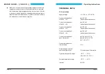
VOR/LOC receiver
Receiver type
triple-conversion
superheterodyne receiver
Frequency range
108.00 MHz - 117.95 MHz
No. of channels
200
Channel spacing
50 kHz
IF-Frequencies 1,2,3
71.05 MHz, 21.4 Mhz,
455 kHz
Sensitivity (audio)
£
-93 dBm for
³
6 dB SINAD
Bandwidth
³
12 kHz at 6 dB
Selectivity
³
65 dB at
D
F
³ ±
50 kHz
BECKER NR 3320 - ( ) / NR 3330 - ( )
Page 28
Issue 12/97
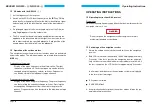
SAFETY PRECAUTIONS
l
Switch off the navigation receiver before starting or shutting
down engines !
l
The NAV system should be connected to the aircraft power supp-
ly by its own 1 A circuit breaker.
l
Warning! Reception is only possible when there is a quasi-optical
sight to the VOR station.
l
When the warning flag in the display unit appears, the course de-
viation needle must then not be used in the continuing flight !
l
Warning! When flying with the autopilot locked on to VOR, the
OBS must not be rotated because any change in the off-course
needle is followed by the autopilot !
l
If the off-course needle instrument fails, no warning flag appears.
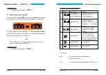
Check the off-course needle by activating the
TEST
function. The
course deviation needle must deflect halfway. Important to check
before approach to landing !
l
During approaches on the back beam, a needle deflection no
longer corresponds to a command indication. In this special
case, course corrections must be made opposite to the needle
deflection !
l
When overflying VOR stations a cone of silence of
±
45°occurs
in which the warning flag appears and the course deviation need-
le stays in the mid position.
l
When flying over mountains the course deviation needle may
deviate about the mid position (reflections) when approaching or
leaving VOR stations. Doppler VOR stations produce substantial-
ly more stable indications under these conditions.
Operating Instructions
Issue 12/97
Page 5