
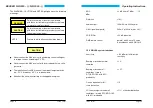
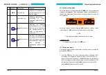

Release the volume control
Call up function “Poti” using the
MDE
key. The following display appe-
ars:
left LC-Display
Poti
right LC-Display
ON or OFF
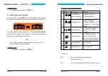
Select the required setting using the
kHz
frequency selector switch and
store the selection by pressing the
STO
key.
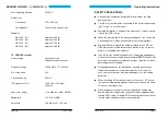
OFF =
The audio output signal is off and can not be
adjusted with the volume control.
ON =
The audio output signal can be adjusted with the
volume control (standard setting).
Ending of the service mode
The navigation receiver must be switched off to finish end the service
mode.
q
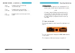
Deletion of all stored frequencies in the storage channels
Press and hold the
STO
and
MDE
keys whilst switching on the navigati-
on receiver. All the stored frequencies in the storage channels are dele-
ted, with the exception of channel 01.
BECKER NR 3320 - ( ) / NR 3330 - ( )
Page 26
Issue 12/97
GENERAL INFORMATIONS
The NAV receiver NR 3320 - (01) is designed to receive and convert
VOR and LOC signals on 200 channels in the frequency range between
108.00 MHz and 117.95 MHz.
The NAV receiver NR 3320 - (02) is designed to receive VOR and LOC
signals on 200 channels in the frequency range between 108.00 MHz
and 117.95 MHz. It supplies the NAV composite signal to an external
VOR/LOC converter. Both NAV receiver include a glideslope receiver.
The glideslope receiver is designed to receive and convert GS signals
on 40 channels in the frequency range between 329.15 MHz and
335.00 MHz.
The NAV receiver NR 3330 - (01) is designed to receive and convert
VOR and LOC signals on 200 channels in the frequency range between
108.00 MHz and 117.95 MHz.
The NAV receiver NR 3330 - (02) is designed to receive VOR and LOC
signals on 200 channels in the frequency range between 108.00 MHz
and 117.95 MHz. It supplies the NAV-composite signal to an external
VOR/LOC converter.
q
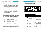
Short description of NAV receiver
The NAV receiver is designed as a single unit for installation in the in-
strument panel or operating console of aircraft. Its dimensions corre-
spond to the ARINC standard dimensions for control equipment. It is
held in place by four DZUS fasteners. All controls and indicators are lo-
cated on the front panel.
Operating Instructions
Issue 12/97
Page 7