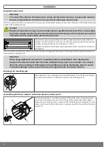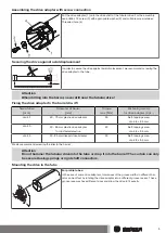
For round tubes:
First notch the tube on the motor side, so the lug of the thrust ring can also be pushed
into the tube. There must be no play between the lug of the thrust ring and the tube.
For rings without drive lugs, which are used to assist fitting on the thrust ring, the bar-
rel must be connected to the thrust ring by a 4.8 x 9.5 mm self-tapping screw.
Assemble the tubular drive with the relevant thrust ring (1) and drive adapter (2). In-
sert the tubular drive with the pre-assembled thrust ring and drive adapter into the
tube to achieve a form fit. Ensure that the thrust ring and drive adapter are secure in
the tube.
Mount the assembled unit comprising barrel, tubular drive and idler on the box and secure the drive according to the type of wall
bracket fixing with a split or spring pin.
Position the barrel so that the roller shutter curtain can be attached with springs or fit the rigid shaft connectors in accordance with
the manufacturer's instructions.
When using springs/anti-lifting devices, we recommend you use at least three; for longer
tubes, use three springs/anti-lifting devices per meter of barrel.
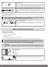
Lay the connecting cable
Lay the connecting cable up to the tubular drive, and fix The connecting cable and
any antennae must not project into the winding chamber. Cover any sharp edges.
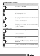
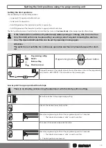
Setting the limit positions with switches
Setting the limit positions
There are
3
ways to set the limit positions:
•
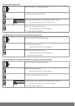
Lower point to upper point without stops
•
Lower point to upper stop
•
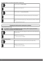
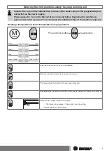
Anti-lifting device in the lower limit position to upper stop
The limit position becomes fixed after the tubular drive has turned off automatically in the desired position three times.
If the tubular drive switches off prematurely while opening or closing, due to an obstruc-
tion, the obstruction can be cleared by reversing a short way and removing the obstruc-
tion. The desired limit position can be set by opening/closing again.
Attention
The switch is not suitable for continuous operation and has only been designed for start-
up.
Programming setting
Switch
Delete setting
Direction arrows
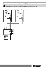
Connect the wires of the tubular drive to those of the same colour in the switch (Item
No. 4901 002 181 0) or operator control and switch on the power supply.
10
Summary of Contents for R12 17C PR+
Page 21: ...Declaration of conformity 21 ...
Page 22: ...22 ...
Page 23: ...23 ...
Page 24: ...2010 300 326 0e 11 07 2016 ...

