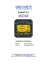
SAR-DF 517
DV 77513.03 Issue 4 09/2006
Page 1-5
1.3.2.
Interface
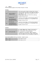
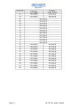
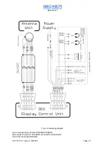
External connections (optional / at Sub-D 9pol. Connector “X4” male)
Dimming:
Pin 8
external voltage for
variable dimming
Analog input signal for variable controlling of the LCD-back-
ground and legends illumination. Input voltage free adjustable
in the range of [1 …33]V at edit menu (Display Control Unit
Page5 edit menu 3.3.5.
Default setting [10…28]V. (10V=Off, 28V=max. dimming)
Impedance of input > 50 k
Ω
Pin 6
night status line
only at SAR-DF 517 N
with NVG frontpanel,
otherwise don’t connect.
Low-active. At input voltage < 2,5V the dimming operates in
night mode. Max. of brightness ca. 2% of day/default mode
Impedance of input > 50 k
Ω
Pin 4
NVG status line
only at SAR-DF 517 N
with NVG frontpanel,
otherwise don’t connect.
Low-active. At input voltage < 2,5V the dimming operates in
NVG mode. Max. of brightness ca. 2% of day/default mode
Impedance of input > 50 k
Ω
Audio/LF:
Pin 7
Audio output signal
AC coupled voltage source with very low inner resistance.
Max. output voltage ca 8V
pp
= 2,83V
RMS
at Volume
Max
.
Max. output power ca. 2W with 4
Ω
speaker.
If a headphone is connected [32…600]
Ω
/ 100mW, we
recommend using a resistor (18
Ω
/ 0,25W) between audio
output and headphone to prevent damaging the headphone.
Serial interface RS232:
(9600 baud, 8 databits, 1 stoppbit, no parity)
Pin 3
Txd
Serial output (ca. ±10V)
Pin 2
Rxd
Serial input (ca. ±10V)

