


SAR-DF 517
DV 77513.03 Issue 4 09/2006
Page 2-5
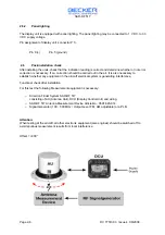
2.4
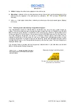
Information for the installation of the antenna Unit
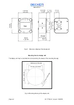
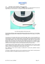
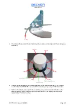
At installation of the antenna Unit the sticker on
(
à
à
N
ß
ß
)
aligns the corresponding drill hole into the
longitudinal axis of the aircraft and in. The direction of flight is (see illustration 2-5).
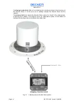
Fig. 2-5 Mounting direction of the antenna unit
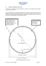
The aircraft manufacturer usually provides information concerning the location of an. It is mandatory
that the following requirements be checked prior to installing the antenna in the absence of any other
information :
The antenna can be mounted either above or below the fuselage, however, as near as possible to the
aircraft centreline. In addition, the selected location should be away from projecting components (fixed
undercarriage, tail plane or radar), and as far away as possible from other antennas. This is essential
to avoid signal distortion and thus inaccurate bearing indication. Furthermore, the antenna and its
feeders must no be located in the vicinity of sources of RF interference such as inverters, motors,
regulators, generators and their wiring. It should also be noted that inverters can give rise to magnetic
interference and thus degrade reception even though good screening may be provided.
In aircraft having wooden or plastic airframe an electric counterweight plate or panel must be located
within the fuselage at the antenna location with minimum dimension 80 x 80 cm. A good connection
between electrical counterweight plate or panel and ground is required.
After installation and test. silicone sealing is recommended to avoid water penetration between
antenna and frame.
In all cases, compliance with FAA AC 43.12-2A requirements will ensure that the mounting location
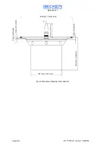
has sufficient strength. The installation dimensions are given in Fig. 2-3.
Direction
Aircraft
Nose