


SAR-DF 517
Page 2-6
DV 77513.03 Issue 4 09/2006
2.5
Installation wiring
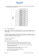
2.5.1.
General
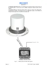
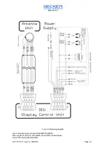
The Fig. 2-6 shows the Interwiring Diagram
Only suitable aircraft cable should be used. Use AWG 22 or AWG 24 for all wiring.
In addition, the following should be observed:
Pull rubber sleeves over the soldered connections on unit connectors.
A fuse or circuit breaker must be installed in the power supply line.
Before switching on the equipment, carefully check the wiring, making particularly sure that
the positive and negative poles have not been confused anywhere.
CAUTION !
No high-frequency cables should be tied in together with the wiring of the direction finder. The
connecting lines must also not be laid together with cables carrying audio signals or pulsed
information (e.g. IFCS, DME, XPR, slaved gyro). The same appliers to the supply and control lines of
autopilotes.