SAR-DF 517
Page 3-8
DV 77513.03 Issue 4 09/2006
3.3.5. Edit menu
The edit menu enables several adjustments. All confirmed changes remain stored even after switching
the device off/on.
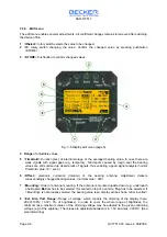
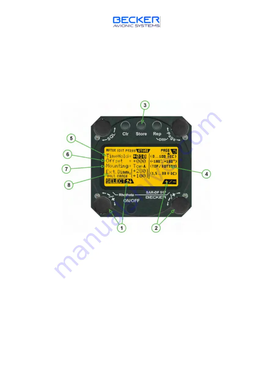
1
>
±±
Select
< rotary switch selects the value to be changed.
2
>
±±
< rotary switch changing the value. Confirm the changed value by pressing pushbutton
>STORE<.
3
>
STORE
< Pushbutton to confirm changed values.
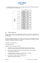
Fig. 3-8 Display edit menu (page 5)
4 Range
of adjustable values.
5
>
TimeHold
< Duration [sec] of internal storage of the averaged bearing value. In case there are
weak signals with signal gaps (e.g. temporary blind spots caused by rough sea) the bearing
values are still summed up despite lack of signals, thus enabling a good signal analysis (normal
TimeHold value: 10 = secs.).
6
>
Offset
< electronic correction (rotation) of the bearing antenna. Adjustment delivers
correspondingly changed bearing values. (normal-value = 000)
7
>
Mounting
< Order of antenna mounting. If the antenna is mounted upside down (e.g. underneath
a helicopter)
Bot
tom has to be selected. If mounted on top of a vehicle,
Top
has to be selected. If
> Mounting< is not properly selected, the bearing value resp. display will be shown mirror inverted!
8
>
Ext. Dim. Volt. Range
< Range of voltage, which controls the dimming of the display (here:
28.0V=100%; 10.0V= 0% of brightness). In order to cover the whole range of brightness, the
minimum resp. maximum values of the dimming voltage may be adapted to the given controlling
voltage (e.g. of the airplane). The values are adjustable between min. 1,5V and max. 33V DC. (See
plan interwiring)

