background image

44

BECKER VADS 1500+

9.5  MEDIA LINES

Lines, hoses, pipes, valves and connections must be checked for damage (leaks) at regular intervals.

It is essential to observe the following instructions when carrying out maintenance and servicing work on media lines:


Damage to media lines must be repaired immediately. Under no circumstances may the VADS 1500+ be operated 
with defective media lines.


Before starting work on media lines, all systems must be depressurised and secured against being switched on again. 
Residual energy must be dissipated or discharged. Residual liquids in media lines must be drained off.

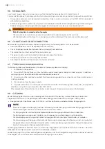
WARNING

Risk of injury due to stored residual energies

The occurrence of mechanical, pneumatic and electrical residual energies on the machine

after operating the unit to stop it in an emergency or after switching off the machine must be observed!

9.6  CONDITIONS FOR RECONNECTION

Before restarting after maintenance and servicing activities, the following points must be observed:


Unauthorised persons are to be expelled from the machine.


Check for proper connection between the machine and the media lines.


The media lines must be checked for leaks and damage.


The power supply must be checked for damage and proper functioning.


All operating materials must have a proper fill level.


All protective devices must be present, functional and tested.

9.7  TEMPORARY IMMOBILISATION

The following steps must be observed in the event of temporary decommissioning:

1.  Shutdown via the operator

2.  To switch off, the machine must be shut down and secured against being switched on again. In addition, a 
warning sign must be attached to the mains disconnection device.

3.  All motors must be individually isolated. Maintenance during operation or when the machine is switched on is 
strictly prohibited.

4.  Disconnection from the power supply

5.  A qualified electrician must disconnect and isolate the motor. After following the 5 safety rules, non-qualified 
electricians may also carry out work on the VADS 1500+.

After completion of the activities, the activities under the point: „Recommissioning“ must be followed.

9.8  CLEANING

Bei der Reinigung der Maschine sind unbedingt alle SicherheitsNOTEe des Kap. 2 dieser Anleitung zu beachten.

Die gesamte Maschine ist in regelmäßigen Abständen abhängig vom Staubanfall zu reinigen. Hierzu gehört: 


Reinigen der aller Oberflächen der VADS 1500+ mit Druckluftpistole und befeuchtetem Reinigungstuch

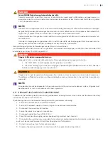
i

NOTE

Eine falsch ausgeführte Reinigung und die Verwendung falscher Reinigungsmittel oder Reinigungsgeräte (z.B. 
Hochdruckreiniger) können zu Schäden an der VADS 1500+ führen.

Für Reinigungsmittel sind die Sicherheitsdatenblätter des Reinigungsmittelherstellers zu beachten.

Die Reinigungsanweisungen der Hersteller von Komponenten und Baugruppen sind zu beachten.

Die Verwendung von Lösungsmitteln oder Reinigungsmitteln die Lösungsmittel enthalten ist verboten. 

Die Verwendung von Reinigungsmitteln, die leichtentzündlich oder generell entflammbar sind, sind verboten!

Die gesetzlichen Vorschriften des Umweltschutzes sind bei der Reinigung zu beachten. Dies gilt insbesondere 
bei der Entsorgung von Reinigungsbetriebsmitteln.

Vor Reinigungsarbeiten ist die VADS 1500+ auszuschalten und gegen einen unerwarteten Anlauf zu sichern. Der DAN-
GERenbereich der Maschine darf erst bei Stillstand betreten werden.

Vor der Reinigung ist zu prüfen, ob Flüssigkeiten ausgelaufen sind. Sind Flüssigkeiten ausgetreten, sind diese zunächst 
zu beseitigen, um ein Ausrutschen bei der weiteren Reinigung zu vermeiden.

Summary of Contents for VARIAIR VADS 1500+

Page 1: ...TRANSLATION OF THE ORIGINAL OPERATING INSTRUCTIONS VADS 1500 SCREW VACUUM PUMPS SCREW COMPRESSORS MAKE IT BECKER en...

Page 2: ...POSAL 18 2 18 BEHAVIOUR IN THE EVENT OF DANGER AND ACCIDENTS 19 2 19 REQUIREMENTS FOR STABILITY 19 2 20 WORKING PROTECTION 19 2 21 AIRBORNE SOUND EMISSIONSN 19 2 22 ERGONOMY 19 3 OPERATING CONDITIONS...

Page 3: ...30 6 3 NORMAL OPERATION 30 6 4 TROUBLESHOOTING 31 6 5 SWITCH OFF MACHINE 31 6 6 RECOMMISSIONING 31 7 CONTROL VADS1500 32 7 1 OPERATING MODES OF THE SCREW UNIT 32 7 2 OPERATION ON THE CONTROLLER DISPL...

Page 4: ...st have read and understood these operating instructions This applies to the machine as well as to purchased components and assemblies Pay special attention to chapter 2 Basic safety instructions In a...

Page 5: ...se operating instructions the following documents and notes must be observed Safety symbols according to chapter 1 3 on the machine as well as on containers for hazardous substances Regulations on acc...

Page 6: ...case i IMPORTANT The operating instructions must always be kept at the place of use and be freely accessible to all persons with tasks on the VADS 1500 The general and local regulations on accident pr...

Page 7: ...itions listed in these operating instructions have been fully implemented in accordance with Directive 2006 42 EC Annex 1 Para 1 7 4 2 i 2 2 OBLIGATIONS OF THE OPERATOR The operator undertakes to only...

Page 8: ...r the respective activity 2 4 QUALIFICATION PERSONNEL Certain activities require a specific qualification to be demonstrated by the personnel carrying them out The following table summarises these qua...

Page 9: ...he VADS 1500 can reach hot surfaces of over 100 C when The specified ambient temperature is exceeded by direct sunlight Failure to maintain minimum distances from adjacent walls Use in heavily pollute...

Page 10: ...breaker is missing The VADS 1500 may only be connected to a mains supply protected by a residual current device RCD Protective measures with residual current devices RCD must be checked for effectiven...

Page 11: ...tures During all work on the VADS 1500 appropriate hand protection must be worn WARNING Risk of injury to feet from crushing and falling objects Foot protection must be worn during all activities on t...

Page 12: ...a transport pallet so that it can be lifted and transported to the final location For internal transport lift the VADS 1500 only at the marked points Lift and transport only by the lifting points 2 11...

Page 13: ...ge DANGER Fire and life hazard due to insufficient distances to neighbouring parts Minimum distances from the product must be maintained to prevent potential fires Minimum distance back wall 50 cm Min...

Page 14: ...the mains disconnection device All motors must be individually isolated Maintenance during operation or when the machine is switched on is strictly prohibited If safety devices have to be dismantled o...

Page 15: ...ing steps are mandatory when preparing for maintenance and servicing activities 1 Switch off the VADS 1500 and all attached assemblies 2 Switch off the power supply and secure it against unintentional...

Page 16: ...ooting for mechanical faults is usually done during set up operation at reduced speed or during normal operation at increased speed In contrast troubleshooting for electrical faults is carried out dur...

Page 17: ...time cannot be guaranteed protective gloves with adequate heat protection must be used WARNING Risk of injury due to stored residual energies The occurrence of mechanical pneumatic and electrical res...

Page 18: ...ng tripping and falling Obstacles and danger spots especially exposed floor slabs and with coolants and lubricants contaminated areas shall be clearly marked The obstacles and danger points are to be...

Page 19: ...ne parts and thus all movements on the system The entire machine can be switched off immediately at the switchgear connection via the mains disconnection device 2 20 REQUIREMENTS FOR STABILITY The VAD...

Page 20: ...ct is controlled via control of the operator If the machine is implemented in a control system by the operator the following conditions apply to the Maintenance operating mode 1 The drive must be disc...

Page 21: ...side outlet 1 Inlet bottom Suction until the inlet plate closes the suction chamber due to the rotor rotation 2 Upper side compression space closes space between rotors casing and outlet plate start o...

Page 22: ...0 4 3 ASSEMBLIES AND COMPONENTS 4 3 1 EXTERIOR VIEW 2 3 4 5 1 Position Designation Position Designation 1 Main switch 4 Ceiling fan 2 Pressure connection rear 5 Touch panel for pump operation 3 Vacuum...

Page 23: ...w valve 2 Oil pressure gauge manometer 8 Oil sight glass 3 Oil pressure switch 9 Ball valve for oil drain 4 Oil pump 10 Air intake filter 5 Compressor unit 11 Oil cooler fan 6 Oil filter with differen...

Page 24: ...ilencer 17 Motor for fan 5 Air intake filter 18 Fan for oil cooler 7 Screw unit 19 Oil cooler 9 Pressure safety valve 20 Oil temperature 10 Pressure silencer 21 Oil filter 11 Frequency converter 22 Di...

Page 25: ...rotation 7 Overflow valve 2 Oil pressure gauge manometer 8 Oil sight glass 3 Oil pressure switch 9 Ball valve for oil drain 4 Oil pump 10 Intake filter 5 Compressor unit 11 Oil cooler fan 6 Oil filte...

Page 26: ...ified immediately All protective equipment must be undamaged fully assembled and functional All protective devices must be checked for functionality damage and completeness after each maintenance of t...

Page 27: ...ting and Disconnect from air supply and electric current 4 5 TESTING OF THE SAFETY AND PROTECTIVE DEVICES i NOTE All safety and protective devices must be checked regularly The condition and function...

Page 28: ...nection DN 150 PN 6 1 Sound level according to EN ISO 2151 90 dB A at 200 Hz and free intake 1 Sound level according to EN ISO 2151 88 dB A at 165 Hz and 800 mbar rel humidity Table 4 2 General techni...

Page 29: ...machine is running Dimensioning of the media lines The diameter of the media lines depends on their length The diameter of the pipes must be at least the same as the nominal connection diameter of th...

Page 30: ...e manufacturer The aspirated media must have a temperature in the range of 5 40 Celsius The product must not be operated in potentially explosive atmospheres The VADS 1500 must be installed horizontal...

Page 31: ...n objects After initial inspection the machine is in a damage free condition This also includes checking the electrical and pneumatic components and connections Expel unauthorised persons from the mac...

Page 32: ...n the controller window This is accessible with extended authorisation Operation with fixed speed adjustable in manual mode and changeable during operation via the setpoint input field in the main win...

Page 33: ...cifying the speed in the input field The screw stage rotates with the frequency entered there Inadmissible setpoint specifications are not possible The main page displays the actual frequency from the...

Page 34: ...xtended rights the parameters of the PID control can be changed here and the behaviour of the PID control can be viewed Information The system information is displayed here Set up Here the settings re...

Page 35: ...or prevents reverse running when the unit is switched off 4 Safety valve If the system pressure rises above the factory set trigger value the solenoid valve in the bypass of the suction line for vacuu...

Page 36: ...ill go Starting the vacuum pump or compressor Initialisation After approx 30 seconds the control unit is booted up and the display shows the main page If all devices in the periphery as well as the co...

Page 37: ...electrical motor an overhaul of the motor is recommended Fault messages If there is a malfunction the Messages button is highlighted in red and the malfunction is made clearly visible in the upper pa...

Page 38: ...supply to the Check forced cooling fan of the drive motor Check fan for short circuit Remove foreign objects from the valve gate Check the set ting of the motor protection switch Oil filter change 22...

Page 39: ...DANGER Risk of slipping due to leaked coolants and lubricants or media The following steps must be followed when preparing for troubleshooting 1 Switch off the VADS 1500 and all attached assemblies 2...

Page 40: ...be switched on again until it has been checked by a qualified electrician Electrical supply line cross section too small The machine must not be switched on again until it has been checked by a qualif...

Page 41: ...on of the phases Foreign bodies sucked into the pump stuck bearings or other components If several components have to be dismantled for the removal of foreign bodies the Be cker service must be notifi...

Page 42: ...e is switched on is strictly prohibited 2 If safety devices have to be dismantled or modified for troubleshooting they must be reattached adjusted and tested immediately after completion of the mainte...

Page 43: ...d tighten Check the accuracy of fit Check that the clamping ring is firmly seated When mounting the filter cover make sure that it is firmly and securely closed Otherwise there could be a danger that...

Page 44: ...3 All motors must be individually isolated Maintenance during operation or when the machine is switched on is strictly prohibited 4 Disconnection from the power supply 5 A qualified electrician must d...

Page 45: ...e angebauten Baugruppen ausschalten 2 Die Stromversorgung ausschalten und gegen unbeabsichtigtes Wiedereinschalten sichern oder den Antrieb von der Versorgungsspannung trennen WARNING Danger due to hi...

Page 46: ...ng and creepage path formation when disconnecting plug connections Always switch off the power supply before disconnecting any plug connections DANGER Danger of slipping due to leaked lubricants If lu...

Page 47: ...duration of decommissioning or storage Duration of decommissioning Measures up to one month No special precautions need to be taken The oil film in the rolling bearings and gearbox can be maintained b...

Page 48: ...separated and disposed of according to the type of waste The local legal regu lations must be observed CAUTION Contamination and damage to the environment by operating materials The operating material...

Page 49: ...eight approx 1200 kg Weight approx 1200 kg Maximum intake pressure 200 mbar abs Maximum intake pressure 1000 mbar abs Minimum intake temperature 5 C Minimum intake temperature 5 C Operating vacuum con...

Page 50: ...MAKE IT BECKER 28100031110 2021 09 28 All rights reserved www becker international com...

Reviews: