


Operating Instructions WSTE 500 and WSTE 1000
22
E
N
G
L
I
S
H
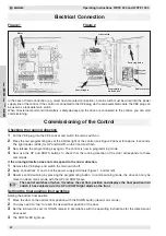
Electrical Connection
Checking the running direction
1
Put the CEE plug into the CEE socket and switch the main switch on.
2
Press the red programming key at the bottom right of the control (see Figure 2 above) for approx. 3 seconds.
The light diodes (LEDs) for UP and DOWN on the front must flash.
3
Now release the programming key again. The control is now in programming mode.
4
Now use the UP and DOWN buttons to check that the running direction of the door corresponds to these
commands.
If the running direction does not correspond to the arrow direction:
1
Remove the CEE plug, and switch the main switch off.
2
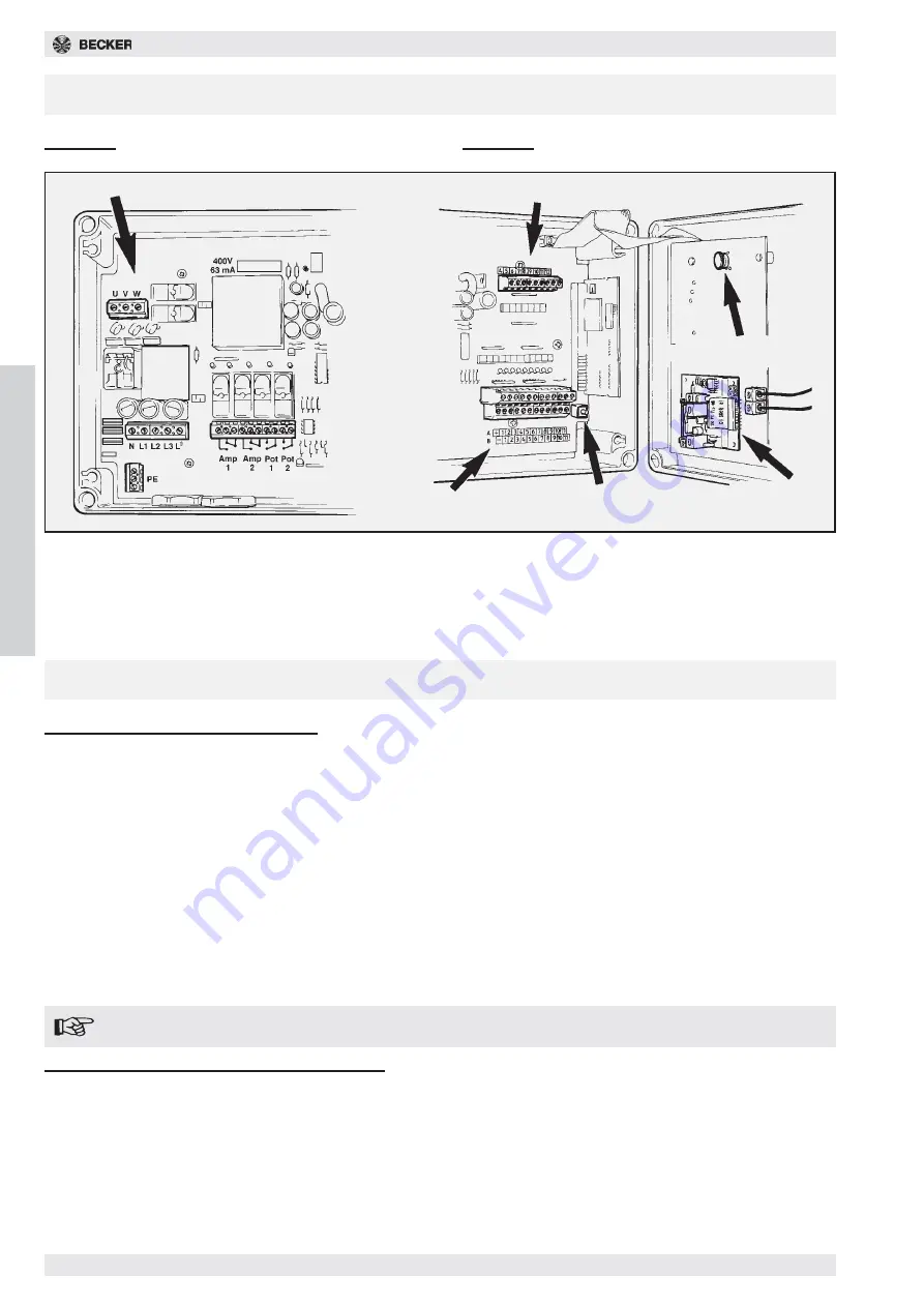
Swap connections L1 and L3 at the power supply terminals (Figure 1, bottom left).
3
Resume commissioning by pressing the programming button. In commissioning mode, the drive can only be
moved in dead man’s mode with the UP and DOWN keys.
The control switches off when it reaches the set final position and displays the final position limit
switch it has contacted via the UP or DOWN light diode on the front.
Setting the final position limit switches
Setting the bottom final position
1
Move the door to the bottom final position with the DOWN button (dead man’s mode).
2
You may need to “tap” to reach the desired final position of the door.
3
Set the limit switch cam for DOWN (black) in accordance with the operating instructions for the direct-mount
drive used.
4
The DOWN LED lights up.
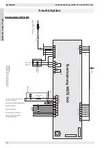
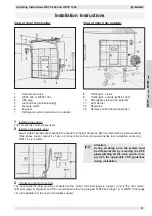
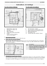
Figure 1
Figure 2
Commissioning of the Control
In the case of fixed connection (e.g. direct flush-mounted connection), a main switch must be wired into the power
supply line of the control. If the control is connected to the CEE plug via the pre-assembled cable, the CEE plug can
be used as a lockable main switch.
When all external command transmitters, safety devices and the drive are connected to the control, you can start
commissioning:
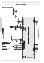
Motor
Programming
mode button
Limit switch
Control inputs
Reclosing delay
Radio receiver


