Operating Instructions WSTE 500 and WSTE 1000
24
E
N
G
L
I
S
H
Functional Description
Connection of external command transmitters
1. Safety contact edge
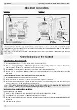
A pneumatic contact or a self-monitoring electrical safety edge can be connected to terminals A1 and B1 (depend-
ing on the programme version). The required sensor is integrated into the WSTE control (self-monitoring, redundant
sensor in accordance with guideline ZH1/494).
In order to ensure monitoring of the rubber helix cable, a resistance of 1.2 kOhm is also provided in terminals A1
and B1. This must be installed in the pressure contact or at the end of the electrical safety edge in accordance with
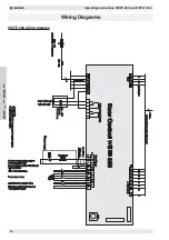
the wiring diagram for WSTE 500 or WSTE 1000. In the case of electrical safety edges ready made ex-works, the
resistance may already be integrated in the safety edge. Therefore, before commissioning, please check that this
has the correct resistance value.
2. Emergency stop button (ZH 1/494 and applicable EN guidelines must be observed)
The WSTE 500 and WSTE 1000 controls can be supplied with an internal emergency stop button. In addition, an
external emergency stop button can be connected to terminals A2 and B2. The jumper between A2 and B2 must
then be removed.
3. Wicket door switch/spring fracture protection
A wicket door switch and the switching contact for the spring fracture protection can be connected to terminals A2
and B2 (all contacts must be connected in series). If these safety devices are installed, the jumper must be re-
moved.
4. Slack cable limit switch
A slack cable limit switch can be connected to terminals A3 and B3. This input has an anti-oscillation device fitted via
an internal time function element of 0.3 seconds. If this safety device is installed, the jumper must be removed.
5. External command transmitter - UP / STOP / DOWN
An additional 3-way push-button can be connected to terminals A4, B4, A5 and B5. This is identical in function to the
function keys on the front of the control. When the door is opened via this UP command, the two-way traffic light
(WSTE 1000) changes to “green-inside”. The control allows exit from the underground garage.
Programming the “self-learning” radio system
The coding of the hand transmitter is specified by the manufacturer. The radio receiver must be set to this code. In
order to programme the hand transmitter coding to the radio receiver, proceed as follows:
1
Briefly
press the “Programme channel 1” button
on the radio receiver.
•
The relevant red signal light
flashes
.
•
You can programme the hand transmitter code
within the next 15 seconds.
2
To do this, press the button on the hand-held trans-
mitter for approx. 2 seconds. The programming of
the hand-held transmitter code is confirmed by illu-
mination of the signal light which was previously
flashing on the receiver.
3
Now release the button on the hand transmitter again.
You can now programme the 4 buttons on the 4-channel receiver in a similar manner. Altogether you can
programme up to 30 different transmitter codes (buttons) per receiver. The 31st code will not be accepted by the
receiver!
If more than 30 transmitter codes are required, we recommend the use of the “self-learning radio - 12 bit”.
Deleting the programmed transmitter codes:
1
Keep the “Programme channel 1” button pressed down.
•
First of all the red signal light flashes slowly.
•
After approx. 5 seconds the red signal light flashes quickly.
•
Continue to keep the button pressed down to confirm the delete process.
•
When the signal light goes out, this means that all codes of the 1-channel receiver and all 4 channels of the
4-channel receiver have been deleted.
2
Only now release the “Programme channel 1” button.

