Operating Instructions WSTE 500 and WSTE 1000
28
E
N
G
L
I
S
H
Functional Principle of Pressure Testing
The pneumatic circuit of the pneumatic safety edge cannot be permanently checked for the control. For this reason,
the performance of pressure testing is prescribed in the industrial sector (ZH 1/494).
In this case, when the control is approx. 5 cm above the floor, it receives the message that the pressure contact
must switch (by contacting the floor) within a prescribed test time (differs according to the control), thus providing
an impulse. When this break impulse is identified by the pressure sensor, the control remains in self-locking mode.
If the reclosing feature is activated on the WSTE 500 or WSTE 1000 control, the door continues to close automati-
cally.
- The pressure test was positive! -
If this break impulse is not identified by the pressure sensor, because e.g. there is a defect in the pneumatic circuit,
the next descent of the door is only performed in dead man’s mode. If the reclosing feature is activated, the door
does not continue to close automatically. The activated reclosing function is no longer performed for safety rea-
sons.
- The pressure test was negative! -
The control can then be reset to self-locking mode by repairing the bottom pneumatic safety edge. When repair has
been effected, either a complete test cycle (in dead man’s mode) must be performed or the control is reset using
Reset (briefly switching off).
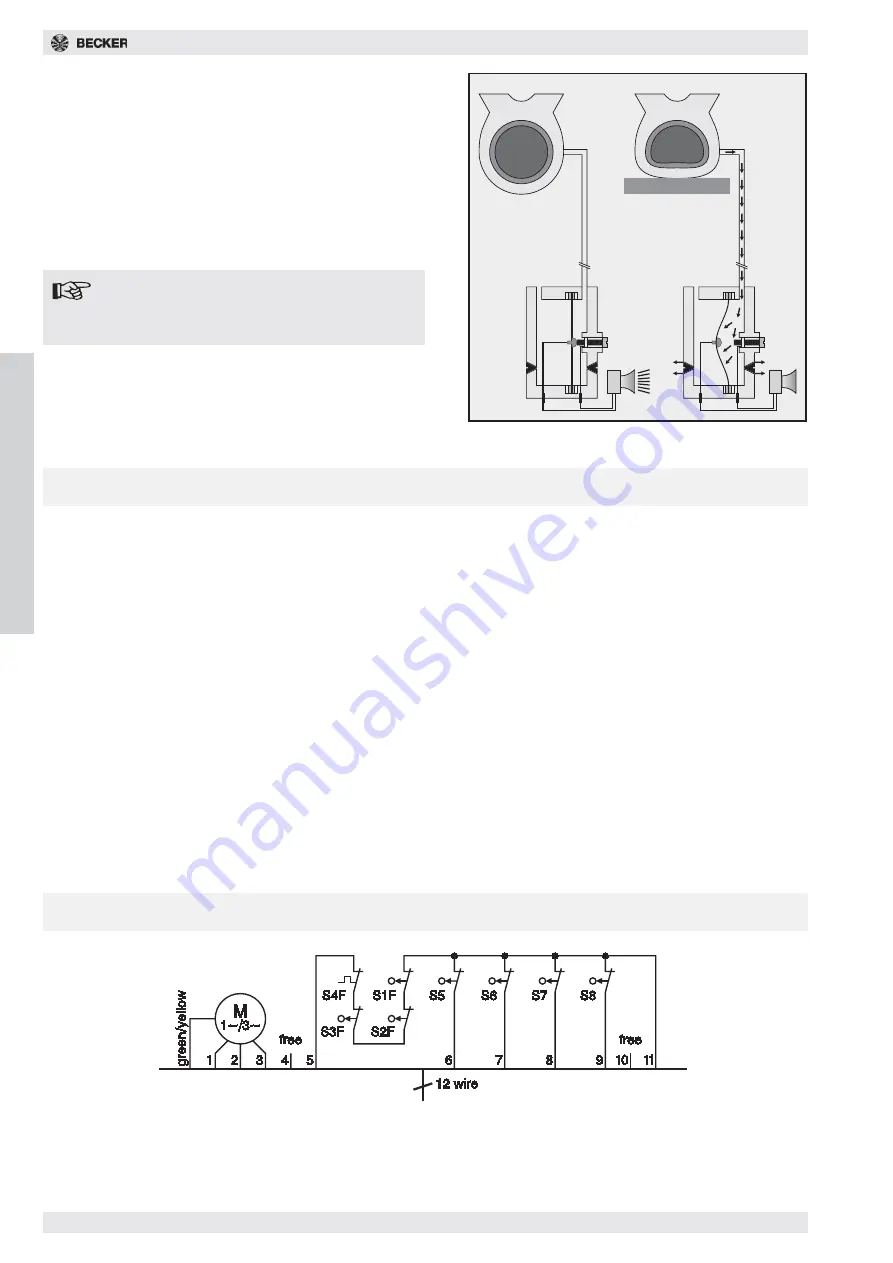
2. The pneumatic circuit
Through the pressure profile which is sealed air-tight on
the lower edge of the door, an air blast is generated by
pressing on the profile. The air is guided over the pres-
sure hose onto the pressure contact. Depending on how
the pressure hose is connected at the pressure contact,
you get a make or break function.
(In the case of the WSTE 500/WSTE 1000 a break func-
tion is required on principle!)
A door control can only detect a defect in the pneumatic
components through pressure testing.
Do not set the pressure contact too sensi-
tively, otherwise if the door does not operate
smoothly it will be triggered by “contact
bounce”.
S1F Safety limit switch OPEN
(yellow switching cam)
S2F Safety limit switch CLOSED (yellow switching cam)
S3F Safety limit switch HK - motor non drive end
S4F Thermal switch in the motor coil
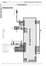
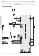
Wiring Diagram
S5 Operating limit switch OPEN (grey switching cam)
S6 Operating limit switch CLOSED (black switching cam)
S7 Function limit switch (orange switching cam)
S8 Function limit switch (green switching cam)

