background image

Basic information 


10 

BK8000 


Mechanical construction 


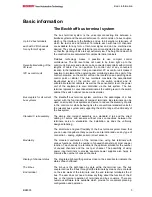
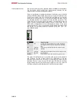
The Beckhoff bus terminal system is remarkable for its compact 
construction and high degree of modularity. When you design the 
installation you will need to plan for one bus coupler and some number of 
bus terminals. The dimensions of the bus couplers do not depend on the 
fieldbus system. If you use large plugs, for example like some of the bus 
plugs used for the Profibus, they may protrude above the overall height of 
the cabinet.  
 

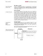
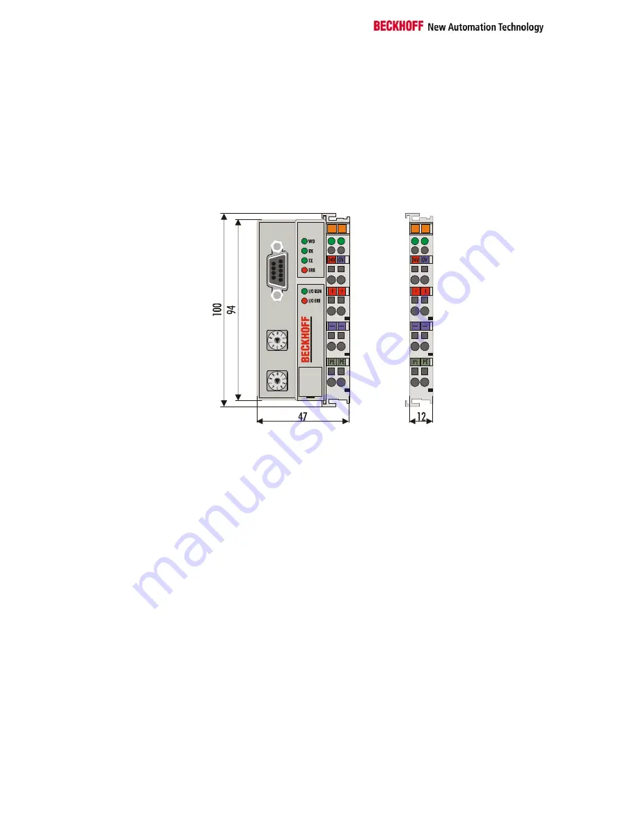
Dimensions of a bus 
coupler 


RS 485

BK

 8000

X1

X10


The overall width of the construction is the width of the bus coupler, 
including the bus end terminal, plus the width of the installed bus terminals. 
The bus terminals are 12 mm or 24 mm wide, depending on their function. 
Depending on the gauge of cables used the overall height of 68 mm may 
be overstepped by about 5 mm to 10 mm by the cables at the front. 
 

Assembly and connections 


It takes only a slight pressure to latch the bus coupler and the various bus 
terminals onto a supporting 35mm C rail and a locking mechanism then 
prevents the individual housings from being removed. You can remove 
them without effort if you first release the latching mechanism by pulling the 
orange tab. You should carry out work on the bus terminals and the bus 
coupler only while they are switched off: if you plug or unplug components 
while the power is on you may briefly provoke some undefined state (and, 
for instance, reset the bus coupler). 
 
You can attach up to 64 bus terminals in series on the right-hand side of 
the bus coupler. When you assemble the components, make sure that you 
mount the housings so that each slot comes together with the 
corresponding key. You cannot make any functional connections merely by 
pushing the housings together along the supporting track. When they are 
correctly mounted there should be no appreciable gap between the 
adjacent housings. 
 
The right-hand side of a bus coupler is mechanically similar to a bus 
terminal. There are eight connections on the top which can be used to 
connect to thick-wire or thin-wire lines. The connection terminals are spring 
loaded. You open a spring terminal by applying a slight pressure with a 
screwdriver or other pointed tool in the opening above the terminal and you 
can then insert the wire into the terminal without any obstruction. When you 
release the pressure the terminal will automatically close and hold the wire 
securely and permanently. 

Summary of Contents for BK8000

Page 1: ...Bus coupler with RS485 interface BK8000 Technical Documentation Version 1 2 2006 10 30...

Page 2: ...Connection 8 K bus contacts 8 Supply isolation 8 The operating modes of the bus coupler 9 Mechanical construction 10 Electrical data 10 The peripheral data in the process image 12 Starting operation...

Page 3: ...cked for consistency with performance data standards or other characteristics None of the statements of this manual represents a guarantee Garantie in the meaning of 443 BGB of the German Civil Code o...

Page 4: ...ed and nullify the liability of Beckhoff Automation GmbH Description of safety symbols The following safety symbols are used in this documentation They are intended to alert the reader to the associat...

Page 5: ...ventional terminal as the cabling level in the switch cabinet the switch cabinet can be made smaller The Beckhoff bus terminal system combines the advantages of a bus system with the functionality of...

Page 6: ...isolation Potential input terminal Power contacts RS485 bus coupler BK8000 Power supply for the bus coupler X1 X10 Bus couplers for various fieldbus systems You can use a variety of bus couplers to at...

Page 7: ...ith spring terminals can be used to supply power to the peripherals The spring terminals are connected in pairs to the power contacts The power supply to the power contacts has no connection to the po...

Page 8: ...xchange of data between the bus coupler and the bus terminals Part of the data exchange takes place via a ring structure within the K bus Disengaging the K bus for example by pulling on one the bus te...

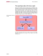
Page 9: ...to test the attached bus terminals the bus terminal test and read in the configuration from which it constructs an internal structure list which is not accessible from outside If an error occurs the b...

Page 10: ...can remove them without effort if you first release the latching mechanism by pulling the orange tab You should carry out work on the bus terminals and the bus coupler only while they are switched off...

Page 11: ...disconnect other power supply points for the duration of the test by drawing the power supply terminals out from the remaining row of terminals by at least 10mm If you do this there will be no need to...

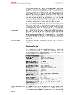
Page 12: ...e oriented The processing of analog signals is always byte oriented and analog input and output values are stored in memory in a two byte representation The values are held as SIGNED INTEGER or twos c...

Page 13: ...s no contradictions is said to be consistent The following consistency is required here 1 The high byte and low byte of an analog value word consistency 2 The control status byte and the corresponding...

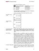
Page 14: ...he pattern of flashes as follows Flashing code Fast flashingq Start of the error code First slow sequence Error code Second slow sequence Error argument Error code Error argument Description 1 pulse 0...

Page 15: ...the serial communication link The 4 communication LEDs indicate the status of RS 485 transfer The operating states are indicated by the WD RX TX and ERROR LEDs WD RX TX ERROR RS 485 LED Operating sta...

Page 16: ...hed from the PC s serial interface to the bus coupler This OCX can be used by all programming languages that operate on the basis of the Microsoft Component Object Model COM specifications You will fi...

Page 17: ...ned from Beckhoff RS 485 transmission Fundamental characteristics of physical data transmission per RS 485 Network topology Linear bus active bus terminator at both ends stubs are possible Medium Scre...

Page 18: ...0 operates as the master and the slave bus coupler must be assigned the address 1 Request In the request the master sends the process output data to be transferred to the slave In the response the sla...

Page 19: ...INTEL format The checksum is generated by adding up the contents of the individual bytes complete response string without checksum byte Any occurring overflow is ignored Status byte of the bus coupler...

Page 20: ...ock Bus terminal 0 1 None POS06 KL3002 Channel 1 2 3 None POS06 KL3002 Channel 2 4 0 POS01 KL1002 Channel 1 4 1 POS01 KL1002 Channel 2 4 2 POS02 KL1002 Channel 1 4 3 POS02 KL1002 Channel 2 4 4 POS03 K...

Page 21: ...70 p Start identifier Byte 3 0x05 3 input data words Byte 4 0x12 Returned message ident Byte 5 0x00 Master address 0 Byte 6 0x Status byte Byte 7 0xXX Data byte 0 Byte 8 0xXX Data byte 1 Byte 12 0xXX...

Page 22: ...l input POS17 2 channel digital input POS18 2 channel digital output POS19 2 channel digital output POS20 2 channel analog output POS21 End terminal In the default settings RS485 RS232 CANopen DevicNe...

Page 23: ...Area for bit oriented data digital inputs Relative byte address Bit position Process image in the control unit Position in the block 4 0 I4 POS02 4 1 I4 POS02 4 2 I4 POS03 4 3 I4 POS03 4 4 I4 POS04 4...

Page 24: ...t significant bits are irrelevant Using the KS2000 configuration software it is possible to insert the third byte into the process image for any chosen channels The least significant byte has control...

Page 25: ...econdary process image This representation is not available in the bus coupler s default setting The KS2000 software is needed The meanings of the registers and of the status bytes are explained in th...

Page 26: ...here Beckhoff Headquarters Beckhoff Automation GmbH Eiserstr 5 33415 Verl Germany phone 49 0 5246 963 0 fax 49 0 5246 963 198 e mail info beckhoff com web www beckhoff com Beckhoff Support Support off...

Reviews: