RS
485 Coupler BK8000
BK8000
17
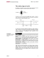
The media: plugs and cable
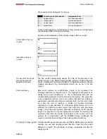
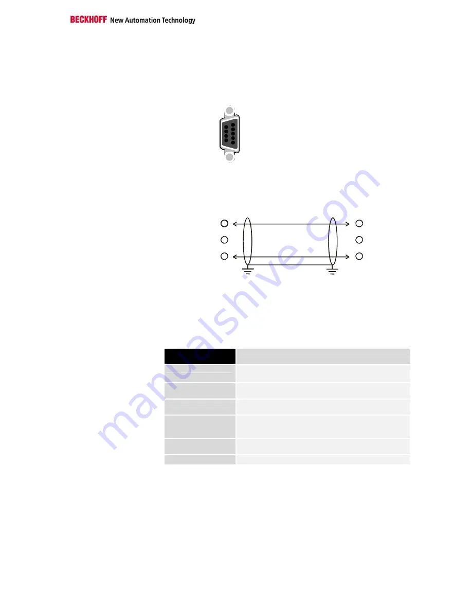
The cable is connected by means of a 9-pole D-sub connector on the left
side of the bus coupler. A screened two-wire cable can be used.
1
6
5: GND
3: RxD/TxD- P
8: RxD/TxD- N
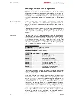
A linear bus can be set-up with the BK8000 Bus Couplers. In order to
prevent reflections during data transmission it is necessary to terminate the
line ends of the bus cable with resistors (120
).
RxD/TxD-P (3)
RxD/TxD-N (8)
GND (5)
Shield
PE
PE
(3) RxD/TxD-P
(5) GND
(8) RxD/TxD-N
Station 1
Station 2
In systems with more than two stations all devices are wired in parallel. In
order to be able to loop through the cable without interruption, two cables
must be connected to one plug. 9-pin D-sub plugs with switchable terminal
resistors, guaranteeing a straightforward cable connection, can be
obtained from Beckhoff.
RS 485
transmission
Fundamental
characteristics of physical
data transmission per
RS 485
Network topology
Linear bus, active bus terminator at both ends, stubs are
possible.
Medium
Screened twisted cable, screening may be omitted,
depending upon the environmental conditions (EMC).
Number of stations
32 in each segment without repeater. With repeaters
extendible up to 99.
Max. bus length
1200
m (extendible with repeaters, please note the
manufacturers recommendations relating to the repeaters
inserted).
Transmission rate
Can be set by software up to 38.4 kbaud (9.6 kbaud,
19.2 kbaud).
Plug connector
9-pin D-sub plug
Please note that the terminal resistance for optimum operation requires a
supply voltage of 5 V DC. These 5 V will be available from the coupler
interface. That is to say, if the plug is removed from the Bus Coupler or the
operating voltage of the Bus Coupler fails, the levels of the terminal
resistances alter and this can adversely affect the transmission by the
remaining bus devices.

