Appendix
24
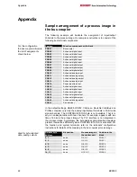
BK8000
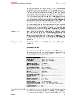
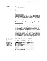
Input data
in the bus coupler
I0
...
byte-oriented
data
...
I3
I4
...
bit-oriented
data
...
I5
The base addresses I0 and O0 listed here are handled as relative
addresses or addresses in the bus coupler. A base peripheral address can
be assigned to the base address of the bus coupler in the bus master
software. All following addresses are automatically assigned the
successive addresses depending on the length of the actual data words.
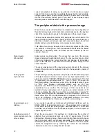
Representation of analog signals in the
process image
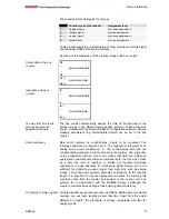
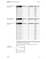
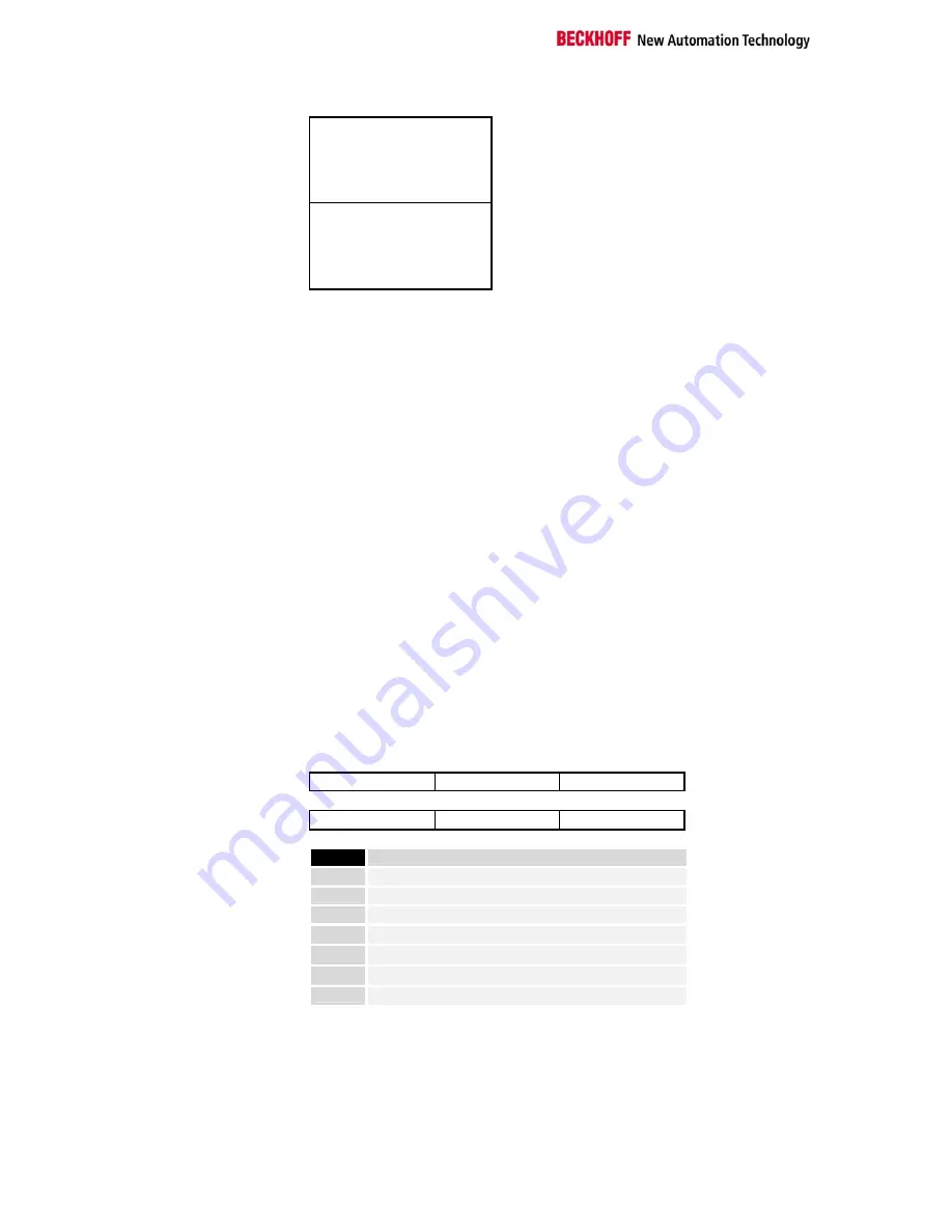
Every analog channel consists of three input bytes and three output bytes
but, in the standard case, one analog channel only occupies one data word
in the process image. These two bytes represent the value as an unsigned
interger, i.e. 15 bits with a sign. The data format is used independently of
the actual resolution. For example: in the case of the resolution of 12 bits,
the four least significant bits are irrelevant. Using the KS2000 configuration
software, it is possible to insert the third byte into the process image for
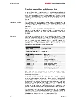
any chosen channels. The least significant byte has control and status
functions. Various operating modes can be set with the control byte. The 6
least significant bytes can by used as addressing bits. Addressing serves
to write and read the register set. The register set has 64 registers and
permits setting of various operating parameters, for example selection of a
thermocouple type or representation of the value in a different number
format. For further information, refer to the corresponding documentation of
the terminals.
I/O bytes of an analog
Output byte 1
Output byte 0
Control byte
channel in the process
image
Input byte 1
Input byte 0
Status byte
Significance of the
BIT 7
0 = NORMAL MODE,
1 = CONTROL MODE
control/status bytes
BIT 6
0 = READ,
1 = WRITE
for accessing
BIT 5
Register address, MSB
the register model
BIT 4
Register address
BIT 3
Register address
BIT 2
Register address
BIT 1
Register address
BIT 0
Register address, LSB


