Product overview
BK9053, BK9103
11
Version: 2.3.0
data in order to manage and store them centrally. This means that it is not necessary to carry out the setting
procedure again if a Bus Terminal is exchanged. The controller carries out the desired setting automatically
after switching on.
2.3
Technical data
System
System data
BK9053
BK9103
Number of I/O modules
only limited by the IP address space
Number of I/O points
depending on controller
Transmission medium
Twisted pair copper cable, 4 x 2, shielded; category 5 (100 Mbaud)
Distance between modules
100 m (between switch and Bus Coupler)
Data transfer rate
10/100 Mbaud
Topology
line or star wiring
Cascading
up to 20 Bus Couplers (max. line length 2 km)
Bus Coupler
Technical data
BK9053
BK9103
Number of Bus Terminals
64 (255 with K-bus extension)
Digital peripheral signals
512 inputs/outputs
512 inputs/outputs
Analog peripheral signals
256 inputs/outputs
256 inputs/outputs
Protocols
PROFINET RT (class B)
TCP-ADS for access via Ethernet with KS2000 configuration software
Configuration possibility
Via the KS2000 configuration software or the controller
Maximum number of bytes
512 bytes of input data and 512 bytes of output data
Bus connection
1 x RJ45
2 x RJ45
Power supply
24 V
DC
(-15%/+20%)
Current consumption
70 mA + (total K bus current)/4, max. 500 mA
Starting current
approx. 2.5 x continuous current
K-Bus power supply up to
1750 mA
Power contact voltage
maximal 24 V
DC
Power contact current load
maximal 10 A
Dielectric strength
500 V (power contact/supply voltage/Ethernet/fieldbus)
Recommended fuse
≤ 10 A
Weight
approx. 100 g
approx. 170 g
on 35 mm mounting rail conforms to EN 60715
Permissible ambient temperature range dur-
ing operation
0 °C ... +55 °C
-25 °C ... +60 °C
Permissible ambient temperature range dur-
ing storage
-25 °C ... +85 °C
-40 °C ... +85 °C
Permissible relative humidity
95 %, no condensation
Vibration/shock resistance
conforms to EN 60068-2-6 / EN 60068-2-27
EMC immunity/emission
conforms to EN 61000-6-2 / EN 61000-6-4
Installation position
variable
Protection class
IP20
Approvals
CE, UL,
, GL
2.4
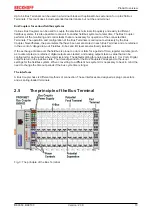
The Beckhoff Bus Terminal system
Up to 256 Bus Terminals, with 1 to 16 I/O channels per signal form
The Bus Terminal system is the universal interface between a fieldbus system and the sensor / actuator
level. A unit consists of a Bus Coupler as the head station, and up to 64 electronic series terminals, the last
one being an end terminal. Up to 255 Bus Terminals can be connected via the K-bus extension. For each

