background image

Installation 


3.2  Installation in the control cabinet 

The Panel PC CP6606-0001-0020 is designed for mounting in control cabinets in machine and plant 
engineering applications. The ambient conditions specified for operation must be observed (see chapter


Technical Data

). 

3.2.1  Preparation of the control cabinet 

The control cabinet wall must be prepared with the required mounting opening  according to the 
Panel PC’s dimensions (see chapter 

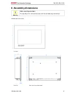
Assembly dimensions

). 

Circulation of air 


Note 

When the unit is installed in an enclosure, adequate space for ventilation must be 
provided. 

The clearance above and below the housing must be at least 5 cm in order to ensure 
adequate ventilation of the Panel PC. 

 
Please note the following points during installation of the Panel PC: 

• 

Position the Panel PC in such a way that reflections on the screen are avoided as far as possible. 

• 

Use the position of the screen as a guide for the correct installation height; it should be optimally 
visible for the user at all times. 

• 

The Panel PC should not be exposed to direct sunlight. 

• 

When the unit is in its mounting position, the ventilation openings must not be obstructed. 

Avoid extreme environmental conditions 


Attention 

Extreme environmental conditions should be avoided as far as possible. Protect the 
Panel PC from dust, moisture and heat. 

The ventilation slots of the Panel PC must not be covered. 


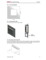
3.2.2  Installation in a control cabinet wall 

For installation of the Panel PC proceed as follows: 

1.  Insert the Panel PC at the intended control cabinet wall position and protect it from falling out, prior to 

final mounting. 

2.  Release the clamping levers, turn the clamping levers to the side and retighten the screws (see 

chapter 

Mounting of the Panel PC

). 

12


CP6606-0001-0020 

Summary of Contents for CP6606-0001-0020

Page 1: ...Installation and Operating instructions for CP6606 0001 0020 Economy Built in Panel PC Version 1 1 Date 2016 10 07...

Page 2: ......

Page 3: ...iew 7 2 2 Appropriate Use 8 2 3 Access to the connectors 8 2 4 Interfaces 9 2 4 1 Power Supply X101 9 2 4 2 Network connection LAN1 X 102 9 2 4 3 EtherCAT connection X 103 9 2 4 4 USB output X 104 X 1...

Page 4: ...8 4 1 3 First switching on and driver installation 18 4 2 Operation 18 4 3 Servicing and maintenance 19 4 3 1 Cleaning 19 4 3 2 Maintenance 19 4 3 3 Replacing the battery on the motherboard 19 4 4 Eme...

Page 5: ...registered trademarks of and licensed by Beckhoff Automation GmbH Other designations used in this publication may be trademarks whose use by third parties for their own purposes could violate the rig...
Page 6: ...Risk of injury WARNING If you do not adhere the safety advise adjoining this symbol there is danger to life and health of individuals Hazard to individuals CAUTION If you do not adhere the safety adv...

Page 7: ...arts of the equipment must first be switched off after which the Panel PC is to be disconnected from the equipment Disconnect the device by unplugging the connectors on the rear side of the Panel PC I...

Page 8: ...not open the housing of the Panel PC Note For technical support contact Beckhoff Service 1 4 1 National regulations Depending on the type of machine and plant in which the Panel PC is used national re...

Page 9: ...sized machines plants or buildings The Panel PC offers the following benefits 7 inch TFT display 800 x 480 WVGA touch screen aluminium front with sheet steel rear cover protection class front side IP...

Page 10: ...ccommodated in a steel housing with aluminium front The Panel PC is installed in the front of control cabinets for wall installation the wall mounting frame with order option C9900 M317 is necessary R...

Page 11: ...onnected to a 10 100BASE T Local Area Network LAN 2 4 3 EtherCAT connection X 103 The RJ 45 connector X103 allows the PC to be connected to an EtherCAT Network 2 4 4 USB output X 104 X 105 The two USB...

Page 12: ...rst unloose the cross head screw 1 The cover plate 2 can now be removed Danger of Explosion WARNING Replace battery only with the identical type or an alternative type recommended by the manufacturer...

Page 13: ...condensation does not form on or inside the device Prior to operation the unit must be allowed to slowly adjust to room temperature Should condensation occur a delay time of approximately 12 hours mus...

Page 14: ...n the Panel PC in such a way that reflections on the screen are avoided as far as possible Use the position of the screen as a guide for the correct installation height it should be optimally visible...

Page 15: ...mping levers For the cutout dimension of the Panel PC see chapter Technical Data the wall thickness is between 1 mm and 5 mm 1 Insert the Panel PC into the cutout 2 Release the clamping levers with a...

Page 16: ...ng frame The wall mounting frame must be flush mounted in the wall and may not overlap the finished plaster A maximum of 5 mm behind the finished plaster can be adjusted with the ball catch Ensure tha...

Page 17: ...3 4 Mounting of the Panel PC The ball catch counter parts are delivered with the wall mounting frame and have to be screwed onto the back side of the CP6606 0001 0020 The needed countersunk head screw...

Page 18: ...ted to the cable 1 Strip insulation from the cable ends Length of stripped conductor is 8 9 mm 2 Screw together the cable ends in the 5 pole plug connector in accordance with wiring diagram Applying t...

Page 19: ...to the Panel PC please adhere to the following order Disconnect the Panel PC from the power supply Connect all cables at the Panel PC and at the devices to be connected Ensure that all screw connectio...

Page 20: ...arning When you have shut down the Panel PC you have to switch off power supply for at least 10 seconds before rebooting the system After resetting power supply the Panel PC will start booting automat...

Page 21: ...y only with the identical type or an alternative type recommended by the manufacturer Notice correct polarity The used battery must be disposed of in accordance with national electronics scrap regulat...

Page 22: ...e Panel PC Cable not connected Check power supply cable 1 Correctly connect cable 2 Call Beckhoff Service Panel PC boots software starts but control does not operate correctly Cause of the fault is ei...

Page 23: ...bly dimensions Notice mounting orientation Warning The assembly of the unit must take place with the orientation diagrammed here All dimensions are in mm Front view Rear view with cutout dimensions Si...

Page 24: ...on 2 USB 2 0 interfaces 1 serial interface RS232 Protection class Front side IP54 rear side IP20 Shock resistance Sinusoidal vibration EN 60068 2 6 10 to 58 Hz 0 035 mm 58 to 500 Hz 0 5 G 5 m s2 Shock...

Page 25: ...Huelshorstweg 20 33415 Verl Germany Phone 49 0 5246 963 0 Fax 49 0 5246 963 198 E mail info beckhoff de Web http www beckhoff de Beckhoff Support Support offers you comprehensive technical assistance...

Page 26: ...nt generates uses and can radiate radio frequency energy and if not installed and used in accordance with the instruction manual may cause harmful interference to radio communications Operation of thi...

Reviews: