background image

Installation and operating instructions | EN

CPX29xx-0000

Multi-touch Control Panel with DVI/USB Extended interface for use in haz-

ardous locations, zone 2/22

4/20/2021 | Version: 0.2

Summary of Contents for CPX29 0000 Series

Page 1: ...Installation and operating instructions EN CPX29xx 0000 Multi touch Control Panel with DVI USB Extended interface for use in haz ardous locations zone 2 22 4 20 2021 Version 0 2...

Page 2: ......

Page 3: ...Description of the interfaces 17 4 3 1 Power supply X101 17 4 3 2 USB out X102 X103 17 4 3 3 USB In X104 18 4 3 4 USB E In X105 18 4 3 5 DVI D In X106 18 4 3 6 Ground 19 5 Mounting and wiring 20 5 1 M...

Page 4: ...Table of Contents CPX29xx 0000 4 Version 0 2 10 2 Connection Kits Connection Cables Accessories 35 10 3 Approvals for USA and Canada 36 10 4 Support and Service 37...

Page 5: ...a diagrams and descriptions in this documentation Trademarks Beckhoff TwinCAT EtherCAT Safety over EtherCAT TwinSAFE XFC and XTS are registered trademarks of and licensed by Beckhoff Automation GmbH O...

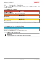
Page 6: ...serious injury WARNING Risk of injury Note this warning Hazard with medium risk of death or serious injury CAUTION Personal injuries Note this warning Hazard with a low degree of risk which could lea...

Page 7: ...Notes on the documentation CPX29xx 0000 7 Version 0 2 1 2 Documentation issue status Version Comment 0 1 Preliminary Version...

Page 8: ...ear side and IP65 at the front side The specified limits for electrical and technical data must be adhered to Potentially explosive atmospheres The Control Panel is only suitable for the following pot...

Page 9: ...e strength of the cables regularly and retightened the cable straps if necessary The Control Panel may only be mounted horizontally see Mounting 20 2 2 2 Special conditions IECEx WARNING Danger of exp...

Page 10: ...CPX29xx 0000 is certified for potentially explosive areas and bears the following markings ATEX BVS 17 ATEX E 119 X Ta 0 55 C II 3G Ex ec IIC T4 Gc II 3D Ex tc IIIC T135 C Dc IECEx IECEx BVS 17 0102 X...

Page 11: ...mponents which may be destroyed by electrostatic discharge when touched Observe the safety precautions against electrostatic discharge according to DIN EN 61340 5 1 3 Working with networks Limit physi...

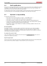
Page 12: ...nnel is instructed regularly about relevant safety aspects and is familiar with the operating manual and in particular the safety instructions contained herein the operation manual is in good conditio...

Page 13: ...kaging should be used Table 1 Dimensions and weight of the individual Panels CPX2915 CPX2919 CPX2921 Dimensions W x H x D 368 2 x 295 3 x 58 mm 438 3 x 369 x 58 mm 543 x 334 7 x 58 mm Weight approx 3...

Page 14: ...d to mount the Control Panel in a control cabinet wall The new Beckhoff panel generation with industry standard multi touch display offers a solution for any application The control panel is also suit...

Page 15: ...w CPX29xx 0000 15 Version 0 2 4 1 Access to the interfaces The interfaces of the Control Panel are located at the rear side of the housing Fig 3 Connection block of the Control Panel CPX29xx 0000 with...

Page 16: ...CPX29xx 0000 is certified for potentially explosive areas and bears the following markings ATEX BVS 17 ATEX E 119 X Ta 0 55 C II 3G Ex ec IIC T4 Gc II 3D Ex tc IIIC T135 C Dc IECEx IECEx BVS 17 0102...

Page 17: ...615810000 The power supply for the Control Panel is established via the socket X101 The power supply connector is included in delivery Pin Signal Pin Signal 1 NC 4 GND Power Supply 2 NC 5 24 VDC 3 4 3...

Page 18: ...CAT5 cables commonly used for Ethernet wiring In the Control Panel the signal is converted back to USB 4 3 5 DVI D In X106 X106 DVI D 3 X 8 pole digital PCB installation MOLEX 74320 9000 74320 9004 Th...

Page 19: ...nction possible with missing ground connection A proper ground connection of the device is absolutely necessary for the correct function of the touchscreen The Control Panel is grounded via the screw...

Page 20: ...adequate space for ventilation must be provided The clearance above and below the housing must be at least 5 cm in order to ensure adequate ven tilation of the Control Panel Please note the following...

Page 21: ...o peripheral equipment Establish a low impedance connection from the earthing point on the Control Panel housing to the central earthing point on the control cabinet wall in which the Panel is being i...

Page 22: ...wrench Proceed as follows 1 Release the clamping levers turn the clamping levers to the side and take out the metal frame Clamping Lever Metal frame Rubber seal 2 Insert the Control Panel into the cu...

Page 23: ...s When connecting cables to the Control Panel please adhere to the following order Disconnect the Control Panel from the power supply Connect all cables at the Control Panel and at the devices to be c...

Page 24: ...cord So the connector is fitted to the cable 1 Strip insulation from the cable ends Length of stripped conductor is 8 9 mm 2 Screw together the cable ends in the 5 pole plug connector in accordance wi...

Page 25: ...ounting bracket Requirements Cable straps Nipper or a side cutter Proceed as follows 1 Connect the USB plugs to the interfaces X102 X103 and X104 2 When the USB plugs are placed fix the USB cables wit...

Page 26: ...ching off while the software is running is very high NOTE Switch off power supply When you have shut down the Industrial PC you have to switch off power supply for at least 10 seconds before rebooting...

Page 27: ...l For hardware problems please contact the Beckhoff Service 6 4 Emergency procedures In case of fire the Control Panel should be extinguished with powder or nitrogen 6 5 Shutting down Disposal Observe...

Page 28: ...ntrol does not operate correctly Cause of the fault is either in the software or in parts of the plant outside the Industrial PC Call the manufacturer of the machine or the software Malfunction of the...

Page 29: ...Assembly dimensions CPX29xx 0000 29 Version 0 2 8 Assembly dimensions CPX2915 0000...

Page 30: ...Assembly dimensions CPX29xx 0000 30 Version 0 2 CPX2919 0000...

Page 31: ...Assembly dimensions CPX29xx 0000 31 Version 0 2 CPX2921 0000...

Page 32: ...atible to the standard DVI output of a PC Interfaces CPX29xx 0000 2 Port USB 3 0 USB 2 0 see Description of the interfaces 17 Protection class Front side IP65 rear side IP20 Shock resistance Sinusoida...

Page 33: ...xplosive atmospheres Part 7 Equipment protection by increased safety e EN 60079 31 2014 Explosive atmospheres Part 31 Equipment dust ignition protection by enclosure t IECEx Standard Description IEC 6...

Page 34: ...ments ANSI UL 60079 0 2020 Explosive atmospheres Part 0 Equipment General requirements ANSI UL 60079 7 2017 Explosive atmospheres Part 7 Equipment protection by increased safety e ANSI UL 60079 31 201...

Page 35: ...ss des USB zu USB E 2 0 Konverters am PC C9900 K626 Connecting kit 20 m for CPX29xx containing 20 m DVI cable 20 m CAT 5 cable for USB E 2 0 USB to USB E 2 0 converter CU8801 for mounting rail install...

Page 36: ...enerates uses and can radiate radio frequency energy and if not installed and used in accordance with the instruction manual may cause harmful interference to radio communications Operation of this eq...

Page 37: ...mponents there Beckhoff Headquarters Beckhoff Automation GmbH Co KG Huelshorstweg 20 33415 Verl Germany Phone 49 0 5246 963 0 Fax 49 0 5246 963 198 e mail info beckhoff com Beckhoff Support Support of...

Page 38: ......

Page 39: ...Beckhoff Automation GmbH Co KG H lshorstweg 20 33415 Verl Germany Phone 49 5246 9630 info beckhoff com www beckhoff com...

Reviews: