Commissioning
EL33xx-00x0
170
Version: 4.2
5.12
Notices on analog specifications
Beckhoff I/O devices (terminals, boxes, modules) with analog inputs are characterized by a number of
technical characteristic data; refer to the technical data in the respective documents.
Some explanations are given below for the correct interpretation of these characteristic data.
5.12.1
Full scale value (FSV)
An I/O device with an analog input measures over a nominal measuring range that is limited by an upper and
a lower limit (initial value and end value); these can usually be taken from the device designation.
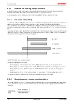
The range between the two limits is called the measuring span and corresponds to the equation (end value -
initial value). Analogous to pointing devices this is the measuring scale (see IEC 61131) or also the dynamic
range.
For analog I/O devices from Beckhoff the rule is that the limit with the largest value is chosen as the full scale
value of the respective product (also called the reference value) and is given a positive sign. This applies to
both symmetrical and asymmetrical measuring spans.
Fig. 180: Full scale value, measuring span
For the above
examples
this means:
• Measuring range 0..10 V: asymmetric unipolar, full scale value = 10 V, measuring span = 10 V
• Measuring range 4..20 mA: asymmetric unipolar, full scale value = 20 mA, measuring span = 16 mA
• Measuring range -200..1370 °C: asymmetric bipolar, full scale value = 1370 °C, measuring span =
1570 °C
• Measuring range -10..+10 V: symmetric bipolar, full scale value = 10 V, measuring span = 20 V
This applies to analog output terminals/ boxes (and related Beckhoff product groups).
5.12.2
Measuring error/ measurement deviation
The relative measuring error (% of the full scale value) is referenced to the full scale value and is calculated
as the quotient of the largest numerical deviation from the true value (‘measuring error’) referenced to the full
scale value.
Summary of Contents for EL33-00 Series
Page 2: ......
Page 6: ...Table of contents EL33xx 00x0 6 Version 4 2...
Page 17: ...Product overview EL33xx 00x0 17 Version 4 2 Fig 10 EL3312 Fig 11 EL3314...
Page 18: ...Product overview EL33xx 00x0 18 Version 4 2 Fig 12 EL3314 0002 Fig 13 EL3314 0010...
Page 61: ...Mounting and wiring EL33xx 00x0 61 Version 4 2 Fig 45 EL3314 0010 Fig 46 EL3314 0090...


