Product overview
EL33xx-00x0
25
Version: 4.2
2.3.2
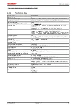
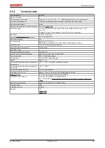
Technical data
Technical data
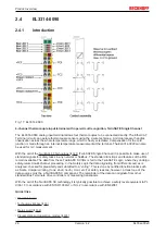
EL3314-0010
Number of inputs
4
Thermocouple sensor types
Types J, K, L, B, E, N, R, S, T, U, C (default setting type K), mV measurement
Input filter limit frequency
1 kHz typ.; depending on sensor length, conversion time, sensor type
Connection technology
2-wire
Maximum cable length to the thermocouple 30 m (
Measuring range
in the range defined in each case for the sensor (default setting: type K; -270 … +1.372
°C)
± 78 mV (10 nV resolution)
Resolution
Internal: 24 bit
Temperature representation: 0.1/0.01/0.001 °C per digit, default 0.01°C
Wiring fail indication
yes
Conversion time
approx. 2.5 s up to 20 ms, depending on configuration and filter setting, default: approx.
250 ms
Voltage measurement
± 78 mV FSV (error: ± 25 µV)
Temperature measurement
Type/ measurement range
Measurement error @ 50 Hz filter and 25 ±
5°C ambient temperature
Typ B: +200...+1820 °C
±5.0 °C
Typ E: -270...+1000°C
±1.8 °C
Typ J: -210...+1200 °C
±1.8 °C
Typ K: -270…+1372 °C
(default)
±1.8 °C
Typ L: -50...+900 °C
±1.8 °C
Typ N: -270…+1300 °C
±2.5 °C
Typ R: -50...+1768 °C
±4.0 °C
Typ S: -50...+1768 °C
±4.0 °C
Typ T: -270…+400 °C
±1.8 °C
Typ U: -50...+600 °C
±1.8 °C
Typ C: 0...+2329 °C
±3.5 °C
The measuring error specified here is a result of several factors, including the measuring
error of the voltage measurement specified above and the accuracy of the temperature
measurement at the cold junction.
Power supply for electronics
via the E-bus
Distributed Clocks
-
Current consumption via E-bus
typ. 200 mA
Bit width in the process data image
max. 24 byte input
Electrical isolation
500 V (E-bus/field voltage)
Configuration
via TwinCAT System Manager
Weight
approx. 60 g
Permissible temperature range during oper-
ation
0 °C ... + 55 °C
Permissible temperature range during stor-
age
-25 °C ... + 85 °C
Permissible relative humidity
95%, no condensation
Dimensions (W x H x D)
approx. 15 mm x 100 mm x 70 mm (width aligned: 12 mm)
on 35 mm mounting rail conforms to EN 60715
Vibration/shock resistance
conforms to EN 60068-2-6 / EN 60068-2-27,
see also
installation instructions for terminals with increased mechanical load capacity
EMC immunity/emission
conforms to EN 61000-6-2 / EN 61000-6-4
Protection class
IP20
Installation position
To ensure enhanced measuring accuracy, the terminal must be installed in the
Approval
CE
Note: FSV = full scale value
Summary of Contents for EL33-00 Series
Page 2: ......
Page 6: ...Table of contents EL33xx 00x0 6 Version 4 2...
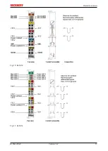
Page 17: ...Product overview EL33xx 00x0 17 Version 4 2 Fig 10 EL3312 Fig 11 EL3314...
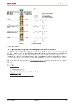
Page 18: ...Product overview EL33xx 00x0 18 Version 4 2 Fig 12 EL3314 0002 Fig 13 EL3314 0010...
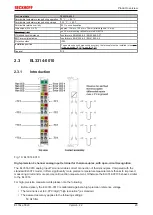
Page 61: ...Mounting and wiring EL33xx 00x0 61 Version 4 2 Fig 45 EL3314 0010 Fig 46 EL3314 0090...


