Product overview
EL33xx-00x0
27
Version: 4.2
CoE object description and parameterization [
2.4.2
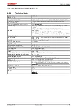
Technical data
Technical data
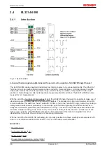
EL3314-0090
Number of inputs
4
Thermocouple sensor types
Types J, K, L, B, E, N, R, S, T, U, C (default setting type K), mV measurement
Input filter limit frequency
1 kHz typ.; depending on sensor length, conversion time, sensor type
Connection technology
2-wire
Maximum cable length to the thermocouple
)
Measuring range
in the range defined in each case for the sensor (default setting: type K; -200 …
+1370°C)
Voltage: ± 30 mV (1 µV resolution) up to ± 75 mV (4 µV resolution)
Resolution
Internal: 16 bit
Temperature representation: 0.1/0.01 °C per digit, default 0.1°C
Note: 16 bit is used for FSV calculation; so, value leaps >0.01°C will occur at reso-
lution 0.01°C depending of which thermocouple is set; e.g. type K: approx. 0.04°C
Wiring fail indication
yes
Conversion time
approx. 2.5 s up to 20 ms, depending on configuration and filter setting, default:
approx. 250 ms
Measuring error
< ±0.3 % (relative to full scale value)
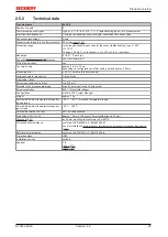
Power supply for electronics
via the E-bus
Distributed Clocks
-
Current consumption via E-bus
typ. 200 mA
Bit width in the process data image
4 x 32 bit TC input, 4 x 16 bit TC output
Electrical isolation
500 V (E-bus/field voltage)
Configuration
via TwinCAT System Manager
Weight
approx. 60 g
Permissible temperature range during operation
-25°C ... +60°C (extended temperature range)
Permissible temperature range during storage
-40°C ... +85°C
Permissible relative humidity
95%, no condensation
Dimensions (W x H x D)
approx. 15 mm x 100 mm x 70 mm (width aligned: 12 mm)
on 35 mm mounting rail conforms to EN 60715
Vibration/shock resistance
conforms to EN 60068-2-6 / EN 60068-2-27,
see also
installation instructions for terminals with increased mechanical load ca-
EMC immunity/emission
conforms to EN 61000-6-2 / EN 61000-6-4
Protection class
IP20
Installation position
variable
Approval
CE
Summary of Contents for EL33-00 Series
Page 2: ......
Page 6: ...Table of contents EL33xx 00x0 6 Version 4 2...
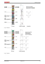
Page 17: ...Product overview EL33xx 00x0 17 Version 4 2 Fig 10 EL3312 Fig 11 EL3314...
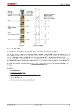
Page 18: ...Product overview EL33xx 00x0 18 Version 4 2 Fig 12 EL3314 0002 Fig 13 EL3314 0010...
Page 61: ...Mounting and wiring EL33xx 00x0 61 Version 4 2 Fig 45 EL3314 0010 Fig 46 EL3314 0090...


