Commissioning
EL3632
131
Version: 2.8
After switching on the 24 V supply voltage or connecting the sensor, a leakage current forms due to the input
capacity on the high-pass filter. This current is based on the physical properties of electrolytic capacitors and
is technically impossible to prevent. This current stabilizes at a constant value within a few minutes, and
during the measurement it generates a constant offset of typically a few mV within the specified tolerance
range. If this offset should prove to be disturbing when analyzing the measurement, it can be permanently
and automatically subtracted out by activating the "Active offset adjustment" (object
A shielded (simple or multiple) sensor cable must be used. The shield should be connected directly at the
shield connections of the terminal.
The red error LED comes on and the error bit is set in the event of an open circuit or if no sensor is
connected. If only the first channel is activated, the red LED for the second channel is disabled in SAFEOP
and OP state.
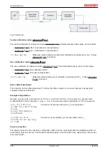
Multi-channel IEPE sensors with a common GND can be connected to the EL3632 if the GND and AGND
connection points are connected via an external bridge:
Unused inputs
Unused inputs must not be short-circuited.
Measuring error
Measuring error < ±0,5% (DC; relative to full scale value), taking into account the Butterworth characteristic.
5.5.1.1
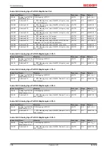
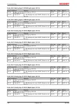
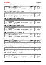
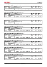
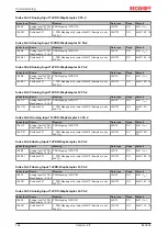
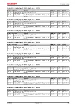
CoE object description
5.5.1.1.1
Profile-specific and parameterization objects
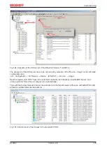
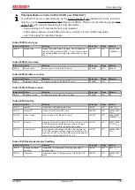
EtherCAT XML Device Description
The display matches that of the CoE objects from the EtherCAT
ommend downloading the latest XML file from the download area of the
and in-
stalling it according to installation instructions.


