Product overview
EL3632
15
Version: 2.8
Fig. 10: Example of ball bearing damage and subsequent analysis
In the example above the so-called envelope enables analysis of shock pulses resulting from unevenness in
the roller bearing. The defective element can be identified based on the periodicity (envelope spectrum).
2.3.3
Output signals of IEPE sensors
Vibrations can be recorded with IEPE (Integrated Electronics Piezo Electric) sensors, for example. The
advantage of this technology is an integrated amplifier as impedance transformer, so that only a simple two-
wire connection (coax) is required for the low-impedance output signal. IEPE sensors are typically supplied
with 2…20 mA constant current. In inactive state they produce a constant DC bias voltage (zero voltage/
U
bias
) typically 7…14 V. Depending on the acceleration of the sensor, an analog AC voltage generated
proportionally to the movement is added to the sensor's U
bias
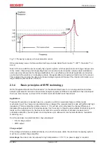
; e.g. a 50 Hz sinusoidal deflection with an
amplitude of 1 g (= 9.81 m/s
2
) produces a 50 Hz sinusoidal output voltage of AC +/-50 mV + U
bias
in the case
of a sensor with a sensitivity of 50 mV/g (Fig.
Output signal of an IEPE sensor (sample)
). The maximum
output signal of a sensor is usually AC +/-5 V (+ U
bias
).
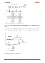
Increasing cable length results in increasing cable capacitance (typically 100 pF/m), so that the control
capability of the integrated amplifier drops with increasing signal frequency. This can be partly compensated
by increasing the supply current (Fig.
Control capability of the IEPE impedance transformer depending on
cable capacitance and supply current
).


