background image

Basics communication

EL3773

25

Version: 2.5

Note

Data management

If slave CoE parameters are modified online, Beckhoff devices store any changes in a fail-
safe manner in the EEPROM, i.e. the modified CoE parameters are still available after a
restart. 
The situation may be different with other manufacturers.

An EEPROM is subject to a limited lifetime with respect to write operations. From typically
100,000 write operations onwards it can no longer be guaranteed that new (changed) data
are reliably saved or are still readable. This is irrelevant for normal commissioning. How-
ever, if CoE parameters are continuously changed via ADS at machine runtime, it is quite
possible for the lifetime limit to be reached. Support for the NoCoeStorage function, which
suppresses the saving of changed CoE values, depends on the firmware version.
Please refer to the technical data in this documentation as to whether this applies to the re-
spective device.

• If the function is supported: the function is activated by entering the code word

0x12345678 once in CoE 0xF008 and remains active as long as the code word is not
changed. After switching the device on it is then inactive. Changed CoE values are not
saved in the EEPROM and can thus be changed any number of times.

• Function is not supported: continuous changing of CoE values is not permissible in view

of the lifetime limit.

Note

Startup list

Changes in the local CoE list of the terminal are lost if the terminal is replaced. If a terminal
is replaced with a new Beckhoff terminal, it will have the default settings. It is therefore ad-
visable to link all changes in the CoE list of an EtherCAT slave with the Startup list of the
slave, which is processed whenever the EtherCAT fieldbus is started. In this way a replace-
ment EtherCAT slave can automatically be parameterized with the specifications of the
user.

If EtherCAT slaves are used which are unable to store local CoE values permanently, the
Startup list must be used.

Recommended approach for manual modification of CoE parameters

• Make the required change in the System Manager

The values are stored locally in the EtherCAT slave

• If the value is to be stored permanently, enter it in the Startup list.

The order of the Startup entries is usually irrelevant.

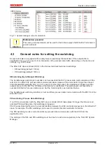
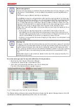
Fig. 15: 

Startup list in the TwinCAT System Manager

The Startup list may already contain values that were configured by the System Manager based on the ESI
specifications. Additional application-specific entries can be created.

Summary of Contents for EL3773

Page 1: ...Documentation EL3773 Power Monitoring Oversampling Terminal 2 5 2018 03 13 Version Date...

Page 2: ......

Page 3: ...er monitoring oversampling EL3773 3 Version 2 5 1 Product overview Power monitoring oversampling EL3773 14 Power monitoring oversampling terminal 6 channel analog input terminal 410 V 410 V 1 5 A 1 5...

Page 4: ...mounting rails 29 5 3 Installation instructions for enhanced mechanical load capacity 32 5 4 Connection 33 5 4 1 Connection system 33 5 4 2 Wiring 35 5 4 3 Shielding 36 5 5 Positioning of passive Ter...

Page 5: ...ngth 131 6 10 7 Temporal aspects of analog digital conversion 132 6 11 Example programs 135 6 11 1 Example 1 Diagnosis and evaluation of input data 136 6 11 2 Commissioning of the example program 139...

Page 6: ...Table of contents EL3773 6 Version 2 5...

Page 7: ...data diagrams and descriptions in this documentation Trademarks Beckhoff TwinCAT EtherCAT Safety over EtherCAT TwinSAFE XFC and XTS are registered trademarks of and licensed by Beckhoff Automation Gm...

Page 8: ...liar with the applicable national standards Description of symbols In this documentation the following symbols are used with an accompanying safety instruction or note The safety instructions must be...

Page 9: ...Oversampling terminals and TwinCAT Scope 2 2 Update programming sample Update structure Update revision status 2 1 Update programming sample Update structure Update revision status 2 0 Migration Updat...

Page 10: ...ormation in the form of an XML file which is available for download from the Beckhoff web site From 2014 01 the revision is shown on the outside of the IP20 terminals see Fig EL5021 EL terminal standa...

Page 11: ...hardware version of I O PCB 1 Unique serial number ID ID number In addition in some series each individual module has its own unique serial number See also the further documentation in the area IP67...

Page 12: ...0020 with serial batch number 26131006 and unique ID number 204418 Fig 5 EP1258 00001 IP67 EtherCAT Box with batch number date code 22090101 and unique serial number 158102 Fig 6 EP1908 0002 IP67 Eth...

Page 13: ...Version 2 5 Fig 7 EL2904 IP20 safety terminal with batch number date code 50110302 and unique serial number 00331701 Fig 8 ELM3604 0002 terminal with unique ID number QR code 100001051 and serial bat...

Page 14: ...s sufficient computing power for true RMS or performance calculation and complex custom algorithms based on the measured voltages and currents Through the oversampling principle the terminal is able t...

Page 15: ...measuring transformer x A AC 1 A AC Max permitted overcurrent max 1 8 A peak value corresponds with 1 2 Arms the upstream use of current limiting current transformers is recommended Current resolutio...

Page 16: ...RMS value rms specifications All AC value specifications in this documentation such as RMS specifications rms refer to a 50 60 Hz 3 phase mains network with a sinusoidal waveform The EL3773 EtherCAT T...

Page 17: ...he measured is referred to N or GND in DC networks Measurement of non sinusoidal amplitude curves including rectangular or DC curves Evaluations and calculations of the raw data sent to the controller...

Page 18: ...8802 3 Pin Color of conductor Signal Description 1 yellow TD Transmission Data 2 orange TD Transmission Data 3 white RD Receiver Data 6 blue RD Receiver Data Due to automatic cable detection auto cros...

Page 19: ...inal for longer than the set and activated SM watchdog time e g in the event of a line interruption the watchdog is triggered and the outputs are set to FALSE The OP state of the terminal is unaffecte...

Page 20: ...the checkbox is not activated nothing is downloaded and the ESC settings remain unchanged Multiplier Multiplier Both watchdogs receive their pulses from the local terminal cycle divided by the watchdo...

Page 21: ...itching off of the SM watchdog via SM watchdog 0 is only imple mented in terminals from version 0016 In previous versions this operating mode should not be used CAUTION Damage of devices and undefined...

Page 22: ...onal Safe Op During transition between Pre Op and Safe Op the EtherCAT slave checks whether the sync manager channels for process data communication and if required the distributed clocks settings are...

Page 23: ...ion values for analog measurement or passwords The order is specified in 2 levels via hexadecimal numbering main index followed by subindex The value ranges are Index 0x0000 0xFFFF 0 65535dez SubIndex...

Page 24: ...of the slave are configurable and writeable This can be done in write or read mode via the System Manager Fig CoE Online tab by clicking This is useful for commissioning of the system slaves Click on...

Page 25: ...on it is then inactive Changed CoE values are not saved in the EEPROM and can thus be changed any number of times Function is not supported continuous changing of CoE values is not permissible in view...

Page 26: ...ine online If the slave is offline The offline list from the ESI file is displayed In this case modifications are not meaningful or possible The configured status is shown under Identity No firmware o...

Page 27: ...ation the placeholder n tends to be used for the individual channel numbers In the CoE system 16 indices each with 255 subindices are generally sufficient for representing all channel parameters The c...

Page 28: ...1 ns Zero point 1 1 2000 00 00 Size 64 bit sufficient for the next 584 years however some EtherCAT slaves only offer 32 bit support i e the variable overflows after approx 4 2 seconds The EtherCAT mas...

Page 29: ...t with highly insulating materials synthetic fibers plastic film etc b Surroundings working place packaging and personnel should by grounded probably when handling with the devices c Each assembly mus...

Page 30: ...k clicks onto the mounting rail If the Terminals are clipped onto the mounting rail first and then pushed together without tongue and groove the connection will not be operational When correctly assem...

Page 31: ...s The six spring contacts of the K Bus E Bus deal with the transfer of the data and the supply of the Bus Terminal electronics The power contacts deal with the supply for the field electronics and thu...

Page 32: ...ts for testing these Power Feed Terminals can be released and pulled at least 10 mm from the group of terminals WARNING Risk of electric shock The PE power contact must not be used for other potential...

Page 33: ...ef and the wire connection should be kept as short as possible A distance of approx 10 cm should be maintained to the cable duct 5 4 Connection 5 4 1 Connection system WARNING Risk of electric shock a...

Page 34: ...on wires when the connector is removed Conductor cross sections between 0 08 mm2 and 2 5 mm2 can continue to be used with the proven spring force technology The overview and nomenclature of the produc...

Page 35: ...t toggle 2 The wire can now be inserted into the round terminal opening without any force 3 The terminal point closes automatically when the pressure is released holding the wire securely and permanen...

Page 36: ...and actors should always be connected with shielded twisted paired wires 5 5 Positioning of passive Terminals Note Hint for positioning of passive terminals in the bus terminal block EtherCAT Termina...

Page 37: ...wer dissipation terminals ensure that an adequate spacing is maintained between other components above and below the terminal in order to guarantee adequate ventilation Optimum installation position s...

Page 38: ...in Fig Recommended distances for standard installation position is recommended Other installation positions All other installation positions are characterized by different spatial arrangement of the m...

Page 39: ...Mounting and wiring EL3773 39 Version 2 5 Fig 29 Other installation positions...

Page 40: ...onnect the EL3773 to the secondary windings of the current trans formers before using the current transformer Fig 30 EL3773 Connection Terminal point Description Comment Name No L1 1 Phase L1 Connecti...

Page 41: ...Mounting and wiring EL3773 41 Version 2 5 Fig 31 Block diagram...

Page 42: ...chapter TwinCAT 2 x regarding this Note EtherCAT XML Device Description If the XML description of the EL3773 is not available in your system you can download the latest XML file from the download area...

Page 43: ...are for automation TwinCAT The Windows Control and Automation Technology will be distinguished into TwinCAT 2 System Manager Configuration PLC Control Programming TwinCAT 3 Enhancement of TwinCAT 2 Pr...

Page 44: ...of the TwinCAT real time driver In order to assign real time capability to a standard Ethernet port of an IPC controller the Beckhoff real time driver has to be installed on this port under Windows T...

Page 45: ...configuration creation section Creating the EtherCAT device 54 in order to view the compatible ethernet ports via its EtherCAT properties tab Adapter button Compatible Devices Fig 35 EtherCAT device p...

Page 46: ...3773 46 Version 2 5 Fig 36 Windows properties of the network interface A correct setting of the driver could be Fig 37 Exemplary correct driver setting for the Ethernet port Other possible settings ha...

Page 47: ...Commissioning EL3773 47 Version 2 5 Fig 38 Incorrect driver settings for the Ethernet port...

Page 48: ...where an EL6601 or similar devices are used it is useful to specify a fixed IP address for this port via the Internet Protocol TCP IP driver setting and to disable DHCP In this way the delay associat...

Page 49: ...current at the time when the TwinCAT build was created For TwinCAT 2 11 TwinCAT 3 and higher the ESI directory can be updated from the System Manager if the programming PC is connected to the Interne...

Page 50: ...ision 1019 or for an older revision The ESI must then be requested from the manufacturer in this case Beckhoff b an ESI is present for the EL2521 0000 device but only in an older revision e g 1018 or...

Page 51: ...ed as follows close all System Manager windows restart TwinCAT in Config mode delete OnlineDescription0000 xml restart TwinCAT System Manager This file should not be visible after this procedure if ne...

Page 52: ...3773 52 Version 2 5 Reasons may include Structure of the xml does not correspond to the associated xsd file check your schematics Contents cannot be translated into a device description contact the fi...

Page 53: ...sence of the actual I O environment drives terminals EJ modules If the configuration is to be prepared in advance of the system configuration as a programming system e g on a laptop this is only possi...

Page 54: ...ion 64 can also be carried out for comparison 6 2 5 OFFLINE configuration creation Creating the EtherCAT device Create an EtherCAT device in an empty System Manager window Fig 48 Append EtherCAT devic...

Page 55: ...ces can be appended by right clicking on a device in the configuration tree Fig 52 Appending EtherCAT devices left TwinCAT 2 right TwinCAT 3 The dialog for selecting a new device opens Only devices fo...

Page 56: ...ion can be displayed as Extended Information Fig 54 Display of device revision In many cases several device revisions were created for historic or functional reasons e g through technological advancem...

Page 57: ...on This also enables subsequent replacement of devices without changing the configuration different specifications are possible for drives Example If an EL2521 0025 1018 is specified in the configurat...

Page 58: ...Commissioning EL3773 58 Version 2 5 Fig 57 EtherCAT terminal in the TwinCAT tree left TwinCAT 2 right TwinCAT 3...

Page 59: ...e Online scanning in Config mode The online search is not available in RUN mode production operation Note the differenti ation between TwinCAT programming system and TwinCAT target system The TwinCAT...

Page 60: ...nning the EtherCAT devices Note Online scan functionality During a scan the master queries the identity information of the EtherCAT slaves from the slave EEPROM The name and revision are used for dete...

Page 61: ...predecessor version s an adaptation of B tsm or even B pro is therefore unnecessary The series produced machines can continue to be built with B tsm and B pro it makes sense to perform a comparative s...

Page 62: ...nfiguration is established and can then be switched to online state OPERATIONAL Fig 68 Config FreeRun query left TwinCAT 2 right TwinCAT 3 In Config FreeRun mode the System Manager display alternates...

Page 63: ...ce is detected i e an EtherCAT slave for which no ESI XML description is available In this case the System Manager offers to read any ESI that may be stored in the device This case is described in the...

Page 64: ...differences are detected they are shown in the correction dialog so that the user can modify the configuration as required Fig 74 Correction dialog It is advisable to tick the Extended Information che...

Page 65: ...s back ward compatible i e newer devices higher revision should be supported if the EtherCAT master addresses them as an older revision The following compatibility rule of thumb is to be assumed for B...

Page 66: ...offers a function Change to Compatible Type for the exchange of a device whilst retaining the links in the task Fig 77 Dialog Change to Compatible Type left TwinCAT 2 right TwinCAT 3 This function is...

Page 67: ...s are now available for configuring the terminal And yet the dimension of complexity of a subscriber determines which tabs are provided Thus as illustrated in the example above the terminal EL3751 pro...

Page 68: ...the start up phase Tick the control box to the left of the input field in order to modify the default value Previous Port Name and port of the EtherCAT device to which this device is connected If it...

Page 69: ...difications include mask out a channel displaying additional cyclic information 16 bit display instead of 8 bit data size etc In so called intelligent EtherCAT devices the process data information is...

Page 70: ...of incorrect con figuration the EtherCAT slave usually refuses to start and change to OP state The System Manager displays an invalid SM cfg logger message This error message invalid SM IN cfg or inva...

Page 71: ...t to the mailbox Move Up This button moves the selected request up by one position in the list Move Down This button moves the selected request down by one position in the list New This button adds a...

Page 72: ...ad and data can be written to the object read write RO The object can be read but no data can be written to the object read only P An additional P identifies the object as a process data object Value...

Page 73: ...rmation If this option button is selected the list of the objects included in the object list of the slave is uploaded from the slave via SDO information The list below can be used to specify which ob...

Page 74: ...flag The current state is now displayed as ERR PREOP When the Clear Error button is pressed the error flag is cleared and the current state is displayed as PREOP again Current State Indicates the cur...

Page 75: ...the input process data If an input is selected the corresponding PDO assignment is displayed in the PDO Assignment list below PDO Assignment PDO assignment of the selected Sync Manager All PDOs define...

Page 76: ...leted from the PDO Assignment list SM Sync Manager to which this PDO is assigned If this entry is empty this PDO does not take part in the process data traffic SU Sync unit to which this PDO is assign...

Page 77: ...ess data and correct operating mode This diagnosis is the same for all slaves as well as function diagnosis typical for a channel device dependent See the corresponding device documentation The colors...

Page 78: ...ocumenta tion A few keywords CoE in the Master for communication with through the Slaves Functions from TcEtherCAT lib Perform an OnlineScan B In the example chosen EL3102 the EL3102 comprises two ana...

Page 79: ...the Master for the Slave concerned and represented there This information cannot be characterized as real time because it is only rarely never changed except when the system starts up is itself determ...

Page 80: ...locally in the slave depends on the device EL terminals except the EL66xx are able to save in this way The user must manage the changes to the StartUp list Commissioning aid in the TwinCAT System Man...

Page 81: ...operation After the operating power is switched on an EtherCAT Slave must go through the following statuses INIT PREOP SAFEOP OP to ensure sound operation The EtherCAT Master directs these statuses in...

Page 82: ...t as standard EtherCAT Master OP Slaves OP This setting applies equally to all Slaves Fig 93 Default behaviour of the System Manager In addition the target state of any particular Slave can be set in...

Page 83: ...e Fig 95 PLC function blocks Note regarding E Bus current EL ES terminals are placed on the DIN rail at a coupler on the terminal strand A Bus Coupler can supply the EL terminals added to it with the...

Page 84: ...a warning message E Bus Power of Terminal is output in the logger window when such a configuration is activated Fig 97 Warning message for exceeding E Bus current Attention Caution Malfunction possib...

Page 85: ...s filter with Bessel characteristic which can be parameterized via the CoE setting 0x8000 15 95 The corresponding anti aliasing filters are placed up or downstream and are adapted automatically The fi...

Page 86: ...case of exchange the EL3773 operates again as foreseen in the application 6 5 Process data Table of contents Data flow 86 Data processing 87 Predefined PDO Assignment 89 Process image 90 Control stat...

Page 87: ...ser GainUser 3 Limit value evaluation 0x80p0 13 95 0x80p0 14 95 Display in the status word 91 of the channel If the value exceeds or falls below these values which can be entered in the indices 0x80p0...

Page 88: ...put Input channel 1 Index 0x6000 03 96 Index 0x6000 05 96 50 V 0x01hex Limit 1 limit value undershot 0x01hex Limit 2 limit value undershot 100 V 0x03hex Limit 1 limit value reached 0x01hex Limit 2 lim...

Page 89: ...x1A61 Synchronous with 2 fold oversampling Synchronous oversampling 4 0x1A00 0x1A03 0x1A10 0x1A13 0x1A20 0x1A23 0x1A30 0x1A33 0x1A40 0x1A43 0x1A50 0x1A53 0x1A61 Synchronous with 4 fold oversampling Sy...

Page 90: ...with the 10 fold oversampling process image and DC timestamp Fig 105 Process image of the EL3773 in the TwinCAT System Manager It is urgently recommended to evaluate the offered diagnostic values in...

Page 91: ...he Distributed Clocks time at which the 5th sample was determined The currently supplied set of 10 samples was started at the time 7 777 216 1 000 000 cycle time 6 777 216 ns The time interval between...

Page 92: ...ks also encompass this EL3773 the terminal then operates synchronously with all other DC devices the sampling clock is derived from the local DC in the EtherCAT slave controller SYNC0 Oversampling SYN...

Page 93: ...ger SM3 As a result the EL3773 can compensate fluctuations in the cycle time to a large extent The EL3773 can thus be used in systems that have no Distributed Clocks functionality The time accuracy of...

Page 94: ...ctionary existence of current XML description use CoE reload for resetting changes Introduction The CoE overview contains objects for different intended applications Objects required for parameterizat...

Page 95: ...t determines the digital filter settings The possible settings are sequentially numbered 0 200 Hz 1 500 Hz 2 1000 Hz 3 1500 Hz 4 2500 Hz 5 5000 Hz 6 15000 Hz See note below UINT16 RW 2500 Hz 4 80p0 17...

Page 96: ...er a synchronization error has occurred during the previous cycle This means a SYNC signal was triggered in the termi nal although no new process data were available 0 OK 1 NOK BOOLEAN RO FALSE 60p0 0...

Page 97: ...ssage 016 Message 50 OCTET STRING 28 RO Index 10F8 Actual Time Stamp Index hex Name Meaning Data type Flags Default 10F8 0 Actual Time Stamp Time stamp UINT64 RO 6 6 5 Standard objects Index 1000 Devi...

Page 98: ...ameter TxPDO UINT8 RO 6 18pp 06 Exclude TxPDOs Specifies the TxPDOs index of TxPDO mapping ob jects that must not be transferred together with this PDO OCTET STRING 2 RO see Predefined PDO Assign ment...

Page 99: ...Index hex Name Meaning Data type Flags Default 1A60 0 AI Timestamp Next Sync1 Time Max Subindex UINT8 RO 1 1A60 01 Subindex 001 1 PDO Mapping entry object 0x6060 AI Inputs entry 0x01 Next Sync1 Time...

Page 100: ...mapping object UINT16 RW 0x1A26 6694dec 1C13 07 SubIndex 007 7 allocated TxPDO contains the index of the associ ated TxPDO mapping object UINT16 RW 0x1A30 6704dec 1C13 08 SubIndex 008 8 allocated TxP...

Page 101: ...8 Command With this entry the real required process data provision time can be measured 0 Measurement of the local cycle time is stopped 1 Measurement of the local cycle time is started The entries 0x...

Page 102: ...10 06 SubIndex 006 Analog input profile 300 UINT32 RW 0x0000012C 300dec F010 07 SubIndex 007 Analog input profile 300 UINT32 RW 0x0000012C 300dec 6 7 Application examples Power measurement at a machin...

Page 103: ...h two current transformers 123 via the connections IL1 and IL2 The sum of all currents in the 3 phase mains network is 0 The value in circuit IL3 can be obtained accordingly by wiring the EL3773 WARNI...

Page 104: ...asured via connections L1 L2 L3 and N The current is measured via three current transformers 123 and the connections IL1 IL2 IL3 and IN star point of the current transformers WARNING WARNING Risk of e...

Page 105: ...ata as in the example here with the EL3102 but n PDOs as in the case of the EL3702 and other oversampling terminals The definition of oversampling by the Beckhoff s point of view shouldn t be mixed up...

Page 106: ...recognizes in its variable browser that the oversampling data is an array package and activates ForceOversampling automatically The array as a whole must be selected using AddSymbol see description in...

Page 107: ...PLC variable within a POU Within the TwinCAT 3 development environment an input variable as an array with respective amount than is given by the oversampling factor have to be defined at first how it...

Page 108: ...f EL3773 Step 2b Creation of a PLC variable via a free task When a POU is not needed onto the particular system a referenced variable could be applied via a free task also If a free task is not existi...

Page 109: ...rty Create symbols must be activated There s a default value given for the Port number 301 that should be changed if necessary This number have to make acquainted for the Scope if applicable later on...

Page 110: ...O U1 Samples of the EL3773 for MAIN aUI_Samples based by the last preceding paragraph Step 2a as illustrated above have to be done in the same way for Var 1 accordingly Step 4 Selection of the PLC arr...

Page 111: ...able aUI_Samples C have to be done Fig 123 Appending the variable aUI_Samples below axis within the scope project of the solution explorer Note Variable don t appears into the target browser If ROUTES...

Page 112: ...ment cycle time The X axis view was fitted properly by using Panning X after the recording was stopped Following the Chart property Use X Axis SubGrid was set to true with 10 divisions as well as the...

Page 113: ...left sided solution explorer I O Devices Device EtherCAT Image Next the register card ADS have to be selected to activate each checkbox Enable ADS Server and Create symbols then the port entry is don...

Page 114: ...of an EtherCAT device Also see Beckhoff Information System 6 8 2 TwinCAT 2 procedure The TwinCAT Scope2 supports the import and display of oversampling process data such as is used by oversampling abl...

Page 115: ...via ADS without further measures since PLC variables are always created as ADS symbols in the background Fig 128 PLC in the System Manager Note the Scope2 can only see such variables in the variable...

Page 116: ...System Manager an instance of it can be assigned to an additional task with a right click It appears in the overview sorted according to bit size Fig 131 Overview of declared types In this example the...

Page 117: ...e task will not run automatically ADS symbol tables are then created for all variables that have this task in their process data images Fig 134 Settings in the additional task Step 2 Configuration in...

Page 118: ...ForceOversampling and DataType INT16 must be set in the channel which has now been created If necessary SymbolBased must be temporarily deactivated in addition Fig 137 Channel settings In order to che...

Page 119: ...issioning EL3773 119 Version 2 5 Fig 138 Activation of the marks An additional example illustrates the following image by representation of an oversampling variable from the EL3751 with 10 x oversampl...

Page 120: ...ng was activated due to the oversampling variable is not provided by the terminal Proceeding with TwinCAT 2 alternatively via ADS In former TwinCAT 2 versions or a lower revision as specified in the t...

Page 121: ...tion tree I O Configuration I O Devices Device EtherCAT Device Image Next the register card ADS have to be selected to activate each checkbox Enable ADS Server and Create symbols then the port entry i...

Page 122: ...versampling record Beckhoff TwinCAT supports the Scope2 with some oversampling devices in a special way by automatically calculating a special ADS array symbol in the background which appears in the S...

Page 123: ...r according to the electricity meter standard DIN 43 856 Current types The EL3773 can measure any type of current Overcurrent limiting factor FS The overcurrent limiting factor FS of a current transfo...

Page 124: ...spective documents Some explanations are given below for the correct interpretation of these characteristic data 6 10 1 Full scale value FSV An I O device with an analog input measures over a nominal...

Page 125: ...ludes the temperature drift a significantly lower measuring error can usually be assumed in case of a constant ambient temperature of the device and thermal stabilization after a user calibration This...

Page 126: ...arge R is used in order to ensure a high impedance For current measurements a small R is used as shunt If the purpose is resistance measurement corresponding considerations are applied Beckhoff genera...

Page 127: ...ntial noiselessness voltage stability At this GND point a wire may be connected to make sure that VCM max is not exceeded in the differential sensor cable If differential channels are not electrically...

Page 128: ...ufactured on the application side to be connected with the right polarity to Signal and Signal It is important to refer to the information page Configuration of 0 4 20 mA differential inputs see docum...

Page 129: ...and related product groups exactly the same Differential EL3x1x 0 20 mA EL3x2x 4 20 mA KL and related product groups exactly the same Preferred current direction because of internal diode Preferred cu...

Page 130: ...Commissioning EL3773 130 Version 2 5 Single ended Differential Fig 147 2 3 and 4 wire connection at single ended and differential inputs...

Page 131: ...der consideration For multi channel terminals boxes with resistive direct ohmic galvanic or capacitive connection between the channels the reference ground should preferably be the symmetry point of a...

Page 132: ...user perspective they all have a common characteristic after the conversion a certain digital value is available in the controller for further processing This digital value the so called analog proces...

Page 133: ...ous or more quickly if the AI channel operates in slow FreeRun mode or more slowly e g with oversampling is then a question of the fieldbus setting and which modes the AI device supports For EtherCAT...

Page 134: ...ated externally with a frequency generator e g as sawtooth or sine A simultaneous square wave signal would be used as reference The signal delay ms s is then the interval between the applied electrica...

Page 135: ...ucts and only serve as examples The notices contained in this document explicitly do not refer to specific applications The customer is therefore responsible for assessing and deciding whether the pro...

Page 136: ...1 Diagnosis and evaluation of input data Download https infosys beckhoff com content 1033 el3773 Resources zip 2041395339 zip Note Usage of this example program This example program was created on a p...

Page 137: ...example the input data of an EL3773 will be checked for validity and processed Cycle time and oversampling freely configurable presetting 5 ms cycle time 20 fold oversampling WC State EtherCAT Master...

Page 138: ...ll other samples are provided with 64 bit DC time stamps these are necessary for determining the frequency Default values are passed on in case of invalid input data the error which occurred is displa...

Page 139: ...hat the settings in the PLC described below do not absolutely have to be changed To start you can jump directly to the item Procedure for starting the program Adaptation of the PLC to the selected ove...

Page 140: ...for the calculation of the respective voltage and current values are made in the MAIN The presets correspond to the standard settings of the EL 3773 rMaxVoltage specifies the maximum measuring voltage...

Page 141: ...splayed and the calculations for the channels can be switched on and off individually Actuating the button labelled with Go to Errors opens the second page of the visualization on which the errors tha...

Page 142: ...t the rear The size of the FIFO buffer can be specified at the beginning and should be selected according to the oversampling factor the cycle time and the connected frequency Important for an accurat...

Page 143: ...user with the global variable CnMaxRecordedValues Example The general equation for the calculation of the RMS value is The respective lower and upper limits for the summation are specified by the size...

Page 144: ...ll not supply any reliable values However the calculation of the frequency of the 50 Hz mains voltage worked reliably in the tests performed The same applies to the determination of the sign of the re...

Page 145: ...tion on this can be found in the corresponding coupler manuals Select the local Ethernet adapter with real time driver if applicable under System configuration I O configuration I O devices Device Eth...

Page 146: ...ing Restarting TwinCAT in RUN mode Fig 165 Generating variable mapping Fig 166 Restarting TwinCAT in RUN mode In TwinCAT PLC under the Project menu select Rebuild all to compile the project Fig Compil...

Page 147: ...Commissioning EL3773 147 Version 2 5 Fig 168 Confirming program start...

Page 148: ...ten Parameter written too low 0x06090032 CoE parameter is too small the firmware limits the values to be written Data can not be transferred or stored to the application because of the present device...

Page 149: ...AT State Machine SAFEOP verification of the sync manager channels and the distributed clocks Outputs remain in safe state on State of the EtherCAT State Machine OP normal operating state mailbox and p...

Page 150: ...2 byte reference to explanatory text from the ESI XML Timestamp 8 byte local slave time or 64 bit Distributed Clock time if available Dynamic parameters added by the firmware The DiagMessages are expl...

Page 151: ...could be stored into a data file hence DiagMessages are available long term for analysis Reading messages into the PLC In preparation Interpretation Time stamp The time stamp is obtained from the loca...

Page 152: ...d 1 Info 4 Warning 8 Error 0 System 1 General 2 Communication 3 Encoder 4 Drive 5 Inputs 6 I O general 7 reserved Error number Example Message 0x4413 Drive Warning Number 0x13 Overview of text IDs Spe...

Page 153: ...deleted Idx 0x X SubIdx 0x X Data deleted 0x117F Information General Information 0x X 0x X 0x X Information 0x1201 Information Communication Communication re es tablished Communication to the field si...

Page 154: ...n 0x2004 Information System s valid IP Configura tion IP d d d d assigned by Dhcp server d d d d Valid IP configuration assigned by the DHCP server 0x2005 Information System s Dhcp client timed out DH...

Page 155: ...the PDO Configuration The selected PDOs do not match the set operating mode Sample Drive operates in velocity mode but the ve locity PDO is but not mapped in the PDOs 0x417F Warning General Warning 0x...

Page 156: ...ive Limit Current Limit current is limited 0x4419 Warning Drive Limit Amplifier I2T model exceeds 100 The threshold values for the maximum current were exceeded 0x441A Warning Drive Limit Motor I2T mo...

Page 157: ...Communication between the fieldbus and the output stage is secured by a Watchdog The axis is stopped automatically if the fieldbus communication is inter rupted The EtherCAT connection was interrupted...

Page 158: ...00 Error Drive Incorrect drive configura tion 0x X d Drive incorrectly configured 0x8401 Error Drive Limiting of calibration ve locity d d Limitation of the calibration velocity 0x8402 Error Drive Eme...

Page 159: ...e not in the correct range 0x8611 Error General IO Output voltage to low Output voltage too low 0x8612 Error General IO Output voltage to high Output voltage too high 0x8613 Error General IO Over curr...

Page 160: ...UL certified without restrictions UL certification according to UL508 with limited power consumption The current consumed by the device is limited to a max possible current consumption of 4 A Devices...

Page 161: ...purpose Generally the slave does not check whether the new data are suitable i e it may no longer be able to operate if the data are unsuitable Simplified update by bundle firmware The update using s...

Page 162: ...vision 0016 The configured identifier must be compatible with the actual device description used as hardware i e the description which the slave has loaded on start up in this case EL3204 Normally the...

Page 163: ...uration is identical otherwise a change dialog appears for entering the actual data in the configuration Fig 177 Change dialog In this example in Fig Change dialog an EL3201 0000 0017 was found while...

Page 164: ...in the following dialog see Fig Selecting the new ESI The checkbox Show Hidden Devices also displays older normally hidden versions of a slave Fig 179 Selecting the new ESI A progress bar in the Syste...

Page 165: ...the slave online Click on the E Bus Terminal whose controller firmware you want to check in the example terminal 2 EL3204 and select the tab CoE Online CAN over EtherCAT Note CoE Online and Offline C...

Page 166: ...CoE directory is managed by the controller and stored in a dedicated EEPROM which is generally not changed during a firmware update Switch to the Online tab to update the controller firmware of a sla...

Page 167: ...date may be accomplished via an rbf file Controller firmware for processing I O signals FPGA firmware for EtherCAT communication only for terminals with FPGA The firmware version number included in th...

Page 168: ...right click the table header and select Properties in the context menu Fig 183 Context menu Properties The Advanced Settings dialog appears where the columns to be displayed can be selected Under Dia...

Page 169: ...terminal must have FPGA firmware version 10 or higher Older firmware versions can only be updated by the manufacturer Updating an EtherCAT device The following sequence order have to be met if no othe...

Page 170: ...nager select the terminal for which the FPGA firmware is to be updated in the example Terminal 5 EL5001 and click the Advanced Settings button in the EtherCAT tab The Advanced Settings dialog appears...

Page 171: ...to the device A download of firmware to an EtherCAT device must not be interrupted in any case If you interrupt this process by switching off power supply or disconnecting the Ethernet link the EtherC...

Page 172: ...version EL3773 Hardware HW Firmware FW Revision no Release date 00 01 EL3773 0000 0002 2011 08 01 05 02 EL3773 0000 0017 2012 09 03 EL3773 0000 0018 2012 10 04 2013 08 05 2013 08 06 EL3773 0000 0019...

Page 173: ...Hex and confirm with OK Fig Entering a restore value in the Set Value dialog All backup objects are reset to the delivery state Fig 187 Entering a restore value in the Set Value dialog Note Alternativ...

Page 174: ...nents there Beckhoff Headquarters Beckhoff Automation GmbH Co KG Huelshorstweg 20 33415 Verl Germany Phone 49 0 5246 963 0 Fax 49 0 5246 963 198 e mail info beckhoff com Beckhoff Support Support offer...

Page 175: ...0 Fig 13 States of the EtherCAT State Machine 22 Fig 14 CoE Online tab 24 Fig 15 Startup list in the TwinCAT System Manager 25 Fig 16 Offline list 26 Fig 17 Online list 27 Fig 18 Spring contacts of th...

Page 176: ...an left TwinCAT 2 right TwinCAT 3 60 Fig 61 Detected Ethernet devices 60 Fig 62 Example default state 60 Fig 63 Installing EthetCAT terminal with revision 1018 61 Fig 64 Detection of EtherCAT terminal...

Page 177: ...n the DC tab 93 Fig 110 EL3773 Selection dialog Predefined PDO Assignment 94 Fig 111 Power measurement at a machine 103 Fig 112 Power measurement with 2 current transformers on a motor 104 Fig 113 Pow...

Page 178: ...ge 132 Fig 150 Signal processing analog input 132 Fig 151 Diagram signal delay step response 134 Fig 152 Diagram signal delay linear 135 Fig 153 Visualization of example program for EL3773 137 Fig 154...

Page 179: ...pdate 164 Fig 179 Selecting the new ESI 164 Fig 180 Display of EL3204 firmware version 165 Fig 181 Firmware Update 166 Fig 182 FPGA firmware version definition 168 Fig 183 Context menu Properties 168...

Reviews: