Commissioning
EL3783
109
Version: 1.1
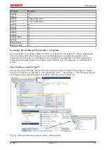
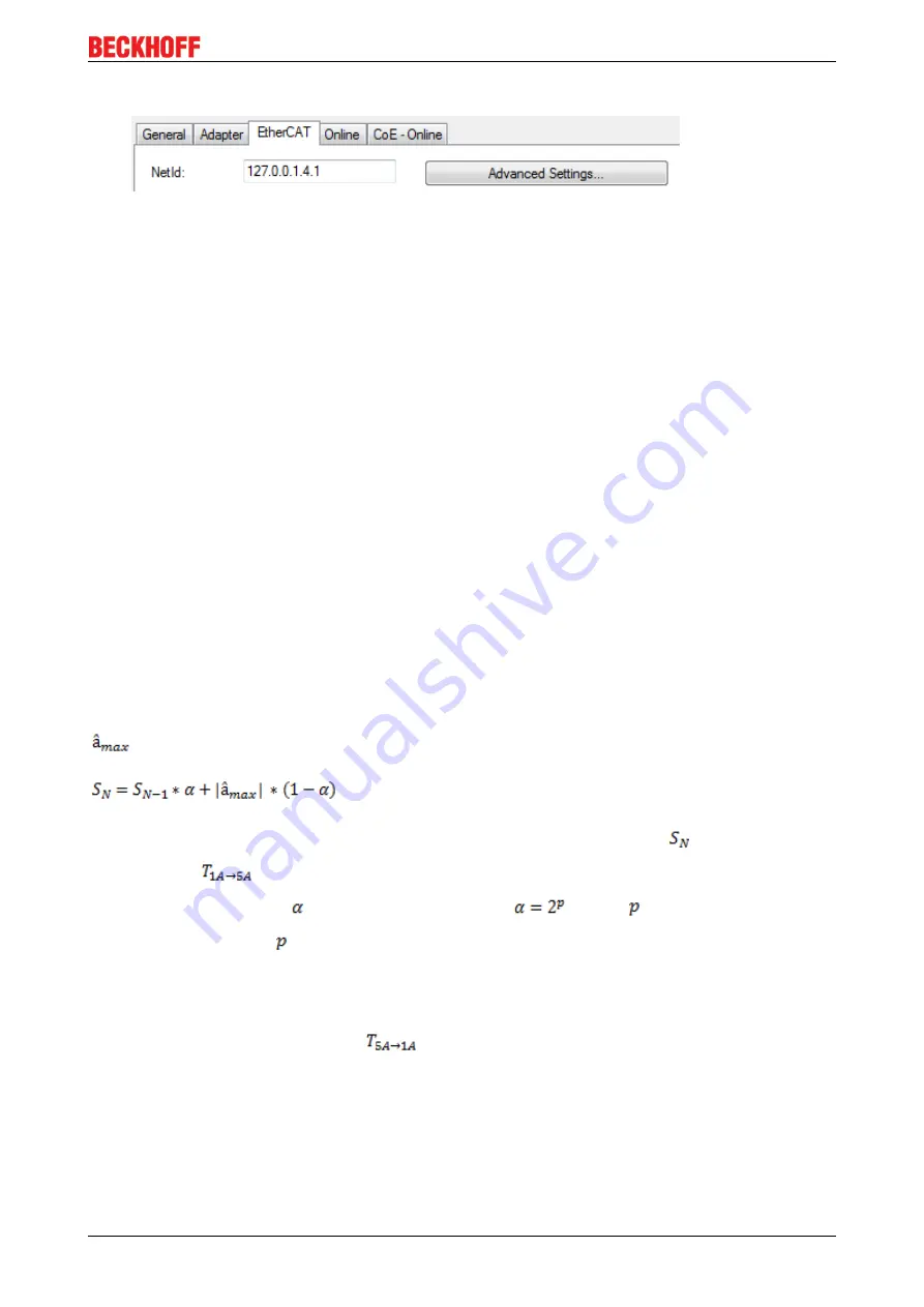
• Checking NetId: the "EtherCAT" tab of the EtherCAT device shows the configured NetId:
.
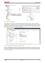
The first 4 numbers have to be identical with the project NetId of the target system. The project NetId
can be viewed within the TwinCAT environment above, where a pull down menu can be opened to
choose a target system (by clicking right in the text field). The number blocks are placed in brackets
there next to each computer name of a target system.
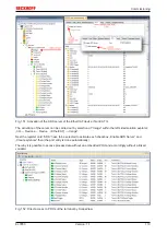
• Modify the NetId: By right clicking on "EtherCAT device" within the solution explorer a context menu
opens where "Change NetId..." have to be selected. The first 4 numbers of the NetId of the target
computer have to be entered; the both last values are 4.1 usually.
Example:
◦ NetId of project: myComputer (123.45.67.89.1.1)
◦ Entry via „Change NetId...“: 123.45.67.89.4.1
Measuring ranges 1 A, 5 A
Fixed current ranges up to 1.3 times the respective rated value for sinusoidal currents. The 1 A range is the
default value on delivery from the factory.
DYN 0
By default the terminal is in the 1 A current measuring range. The terminal switches over to the 5 A
measuring range as soon as the current in one of the three channels exceeds the permanently coded
threshold value T
1A→5A
of approx. 1.74 A (momentary). The switchover takes 250 µs at the most. Switching
back takes place as soon as the maximum values of a full half-wave on all the current channels lie below the
threshold value T_(5A→1A) of approx. 1.69 A (momentary).
DYN1, DYN2, DYN3
By default the terminal is in the 1 A current measuring range. The terminal determines the maximum value of
the current separately for each half-wave and each current channel. The determined maximum values
for each half-wave are averaged channel-by-channel with an exponential filter of the form.
The terminal switches over to the 5 A measuring range as soon as the filtered value
exceeds the
threshold value
. The difference between the characteristics for the switchover is due to the choice
of the respective coefficients
. The coefficient is formed by
, where
is the constant from the
name of the setting ("DYN
"). In turn, it follows that the setting variant DYN 3 requires more half-waves
exceeding the threshold value in order to switch over than a smaller setting such as DYN 1.
Switching from the 5 A measuring range back to the 1 A measuring range takes place analogously with the
aid of the filter. Switching back takes place as soon as the average of the maximum values of all the current
channels lies below the threshold value
.
The settings DYN1, DYN2 and DYN3 are intended for current measurements in grids in which temporary
current peaks occur. However, these peaks should not cause any direct switchover of the terminal. If there
should be an error that results in a lengthy fault current, however, the terminal will switch over.


