Commissioning
EL47xx
108
Version: 2.7
5.4
Oversampling terminals/boxes and TwinCAT Scope
Generally input data of a terminal/box could be achieved by the scope either directly (via the activated ADS
server) or by creation of a PLC variable which is linked to the PDO of a terminal/box for recording them. Both
procedures will be explained for TwinCAT 3 (TC3) at first and for TwinCAT 2 (TC2) respectively.
Oversampling means that an analog or digital input device supplies not only one measured value for each
process data cycle/EtherCAT cycle (duration T), but several, which are determined at a constant interval
t < T. The ratio T/t is the oversampling factor n.
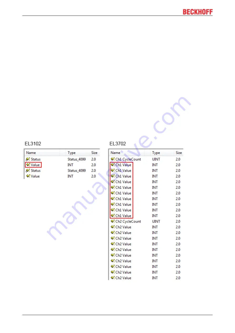
A channel thus offers not only one PDO for linking in the process data, as in the example here with the
EL3102, but n PDOs as in the case of the EL3702 and other oversampling terminals/boxes.
The definition of “oversampling” by the Beckhoff’s point of view shouldn’t be mixed up with the oversampling
process of a deltaSigma ADC:
•
deltaSigma ADC
: the frequency used by the ADC to sample the analogue signal is faster than a
multiple times than the frequency of the provided digital data (typically in kHz range). This is called
oversampling resulting by the functional principle of this converter type and serve amongst others for
anti-aliasing.
•
Beckhoff
: the device/ the terminal/box read of the used ADC (could be a deltaSigma ADC also) digital
sample data n-times more than the PLC/ bus cycle time is set and transfers every sample to the control
– bundled as an oversampling PDO package.
For example these both procedures are arranged sequentially by their technical implementation within the
EL3751 and can also be present simultaneously.
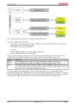
Fig. 133: Oversampling PDO of the EL37xx series and in the comparison with EL31xx
Accordingly the Scope2 (TC2) or ScopeView (TC3) can read in and display several PDOs per cycle in
correct time.
Summary of Contents for EL47 Series
Page 1: ...Documentation EL47xx Analog output terminal with oversampling 2 7 2020 02 27 Version Date...
Page 2: ......
Page 33: ...Mounting and wiring EL47xx 33 Version 2 7 Fig 23 Other installation positions...
Page 70: ...Commissioning EL47xx 70 Version 2 7 Fig 73 Incorrect driver settings for the Ethernet port...
Page 149: ...Commissioning EL47xx 149 Version 2 7 Fig 184 Process data tab SM1 EL47xx...


