background image

Commissioning

EL6201

96

Version: 2.2

Status

Description

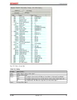
No Carrier / Open

No carrier signal is available at the port, but the port
is open.

No Carrier / Closed

No carrier signal is available at the port, and the port
is closed.

Carrier / Open

A carrier signal is available at the port, and the port is
open.

Carrier / Closed

A carrier signal is available at the port, but the port is
closed.

File Access over EtherCAT

Download

With this button a file can be written to the EtherCAT
device.

Upload

With this button a file can be read from the EtherCAT
device.

"DC" tab (Distributed Clocks)

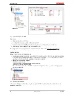
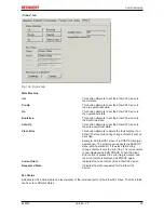
Fig. 134: "DC" tab (Distributed Clocks)

Operation Mode 

Options (optional):

• FreeRun

• SM-Synchron

• DC-Synchron (Input based)

• DC-Synchron

Advanced Settings… 

Advanced settings for readjustment of the real time determinant TwinCAT-
clock

Detailed information to Distributed Clocks are specified on 

http://infosys.beckhoff.com

:

Fieldbus Components

 → EtherCAT Terminals → EtherCAT System documentation → EtherCAT basics →

Distributed Clocks

5.2.7.1

Detailed description of Process Data tab

Sync Manager

Lists the configuration of the Sync Manager (SM).
If the EtherCAT device has a mailbox, SM0 is used for the mailbox output (MbxOut) and SM1 for the mailbox
input (MbxIn).
SM2 is used for the output process data (outputs) and SM3 (inputs) for the input process data.

If an input is selected, the corresponding PDO assignment is displayed in the 

PDO Assignment

 list below.

PDO Assignment

PDO assignment of the selected Sync Manager. All PDOs defined for this Sync Manager type are listed
here:

Summary of Contents for EL6201

Page 1: ...Documentation EL6201 AS Interface Master Terminal 2 2 2017 03 30 Version Date...

Page 2: ......

Page 3: ...mounting rails 27 4 3 Installation instructions for enhanced mechanical load capacity 30 4 4 Connection system 31 4 5 Prescribed installation position 34 4 6 Mounting of Passive Terminals 35 4 7 LEDs...

Page 4: ...t 130 5 7 2 Configuration data 130 5 7 3 Command object 134 5 7 4 Input data 137 5 7 5 Output data 137 5 7 6 Information data 137 5 7 7 Diagnostic data 138 5 7 8 ASI data 141 5 8 Object description st...

Page 5: ...data diagrams and descriptions in this documentation Trademarks Beckhoff TwinCAT EtherCAT Safety over EtherCAT TwinSAFE XFC and XTS are registered trademarks of and licensed by Beckhoff Automation Gm...

Page 6: ...liar with the applicable national standards Description of symbols In this documentation the following symbols are used with an accompanying safety instruction or note The safety instructions must be...

Page 7: ...ad capacity Update revision status 1 4 Update chapter Technical data Section Connection updated Update revision status 1 3 Update chapter Technical data Update chapter Object description and parameter...

Page 8: ...ormation in the form of an XML file which is available for download from the Beckhoff website From 2014 01 the revision is shown on the outside of the IP20 terminals see Fig EL5021 EL terminal standar...

Page 9: ...his PCB hardware version of I O PCB 1 Unique serial number ID ID number In addition in some series each individual module has its own unique serial number See also the further documentation in the are...

Page 10: ...g 4 EL3202 0020 with batch numbers 26131006 and unique ID number 204418 Fig 5 EP1258 00001 IP67 EtherCAT Box with batch number 22090101 and unique serial number 158102 Fig 6 EP1908 0002 IP76 EtherCAT...

Page 11: ...11 Version 2 2 Fig 7 EL2904 IP20 safety terminal with batch number date code 50110302 and unique serial number 00331701 Fig 8 ELM3604 0002 terminal with ID number QR code 100001051 and unique serial...

Page 12: ...nterface master terminal The EL6201 AS interface master terminal enables the direct connection of AS interface slaves The AS Interface compliant interface supports digital and analog slaves according...

Page 13: ...technology Data transfer rates 167 kbit s Distributed clocks Power contacts no Electrical isolation 500 V AS Interface E bus Supply voltage for electronics via the E bus Current consumption 120 mA E...

Page 14: ...m proves to be a technically and economically practical supplement to the normal fieldbus The freely selectable network topology and its simple configuration facilitate the installation of an AS i net...

Page 15: ...y Assembly example Fig 13 Upper and lower half of the AS i component are disassembled Fig 14 The AS i cable is placed always without error thanks to its profiling in the lower half of the AS i compone...

Page 16: ...receiver with regard to a parity bit and several further independent variables This ensures extremely high reliability in the detection of single and multiple errors The use of the AS Interface in ver...

Page 17: ...8802 3 Pin Color of conductor Signal Description 1 yellow TD Transmission Data 2 orange TD Transmission Data 3 white RD Receiver Data 6 blue RD Receiver Data Due to automatic cable detection auto cros...

Page 18: ...inal for longer than the set and activated SM watchdog time e g in the event of a line interruption the watchdog is triggered and the outputs are set to FALSE The OP state of the terminal is unaffecte...

Page 19: ...the checkbox is not activated nothing is downloaded and the ESC settings remain unchanged Multiplier Multiplier Both watchdogs receive their pulses from the local terminal cycle divided by the watchdo...

Page 20: ...itching off of the SM watchdog via SM watchdog 0 is only imple mented in terminals from version 0016 In previous versions this operating mode should not be used CAUTION Damage of devices and undefined...

Page 21: ...onal Safe Op During transition between Pre Op and Safe Op the EtherCAT slave checks whether the sync manager channels for process data communication and if required the distributed clocks settings are...

Page 22: ...ion values for analog measurement or passwords The order is specified in 2 levels via hexadecimal numbering main index followed by subindex The value ranges are Index 0x0000 0xFFFF 0 65535dez SubIndex...

Page 23: ...recommended for modifications while the system is running or if no System Manager or operating staff are available If slave CoE parameters are modified online Beckhoff devices store any changes in a f...

Page 24: ...on it is then inactive Changed CoE values are not saved in the EEPROM and can thus be changed any number of times Function is not supported continuous changing of CoE values is not permissible in view...

Page 25: ...ine online If the slave is offline The offline list from the ESI file is displayed In this case modifications are not meaningful or possible The configured status is shown under Identity No firmware o...

Page 26: ...ation the placeholder n tends to be used for the individual channel numbers In the CoE system 16 indices each with 255 subindices are generally sufficient for representing all channel parameters The c...

Page 27: ...highly insulating materials synthetic fibers plastic film etc b Surroundings working place packaging and personnel should by grounded probably when handling with the devices c Each assembly must be te...

Page 28: ...licks onto the mounting rail If the Terminals are clipped onto the mounting rail first and then pushed together without tongue and groove the connection will not be operational When correctly assemble...

Page 29: ...e six spring contacts of the K Bus E Bus deal with the transfer of the data and the supply of the Bus Terminal electronics The power contacts deal with the supply for the field electronics and thus re...

Page 30: ...for testing these Power Feed Terminals can be released and pulled at least 10 mm from the group of terminals WARNING Risk of electric shock The PE power contact must not be used for other potentials 4...

Page 31: ...strain relief and the wire connection should be kept as short as possible A distance of approx 10 cm should be maintained to the cable duct 4 4 Connection system WARNING Risk of electric shock and da...

Page 32: ...res when the connector is removed Conductor cross sections between 0 08 mm2 and 2 5 mm2 can continue to be used with the proven spring force technology The overview and nomenclature of the product nam...

Page 33: ...g the wire securely and per manently Terminal housing ELxxxx KLxxxx ESxxxx KSxxxx Wire size width 0 08 2 5 mm2 0 08 2 5 mm2 Wire stripping length 8 9 mm 9 10 mm High Density Terminals ELx8xx KLx8xx HD...

Page 34: ...e ventilation Prescribed installation position The prescribed installation position requires the mounting rail to be installed horizontally and the connection surfaces of the EL KL terminals to face f...

Page 35: ...ve part in data transfer within the bus terminal block are so called Passive Terminals The Passive Terminals have no current consumption out of the E Bus To ensure an optimal data transfer you must no...

Page 36: ...green This LED lights up during the AS i data exchange phase it flickers in regular operation Set switch green This LED is on as long as both set inputs are short circuited AS i Power green This LED...

Page 37: ...riefly bridging contacts 1 and 5 2 and 6 ASi ASi connection brown Both terminal points identified with ASi are connected internally 3 and 7 ASi ASi connection blue Both terminal points identified with...

Page 38: ...i Connection AS i Both terminal points identified with ASi are connected internally 3 ASi Connection AS i Both terminal points identified with ASi are connected internally 4 not used 5 Uin Negative vo...

Page 39: ...520 left connection to AS i power supply unit right Since the user data are modulated on the power supply line with the AS Interface a special AS i power supply unit 30 5 VDC is required A further pos...

Page 40: ...ger I O Configuration In particular TwinCAT driver installation Fieldbus components Fieldbus Cards and Switches FC900x PCI Cards for Ethernet Installation Devices contain the terminals for the actual...

Page 41: ...d on the following sample configuration the subsequent subsections describe the procedure for TwinCAT 2 and TwinCAT 3 Control system PLC CX2040 including CX2100 0004 power supply unit Connected to the...

Page 42: ...ch case the EK1100 coupler wouldn t be necessary 5 1 1 TwinCAT 2 Startup TwinCAT basically uses two user interfaces the TwinCAT System Manager for communication with the electromechanical components a...

Page 43: ...e made known first In the menu under Actions Choose Target System via the symbol or the F8 key open the following window Fig 43 Selection of the target system Use Search Ethernet to enter the target s...

Page 44: ...have to be set to Config mode via or via menu Actions Set Reset TwinCAT to Config Mode Shift F4 Fig 45 Select Scan Devices Confirm the warning message which follows and select EtherCAT in the dialog F...

Page 45: ...en reads the elements present in the configuration below Fig 48 Reading of individual terminals connected to a device This functionality is useful if the actual configuration is modified at short noti...

Page 46: ...t Editor CFC Sequential Function Chart SFC The following section refers to Structured Text ST After starting TwinCAT PLC Control the following user interface is shown for an initial project Fig 49 Twi...

Page 47: ...cessful compilation TwinCAT PLC Control creates a tpy file in the directory in which the project was stored This file tpy contains variable assignments and is not known to the System Manager hence the...

Page 48: ...Manager The two variables bEL1004_Ch4 and nEL2008_value can now be assigned to certain process objects of the I O configuration Assigning variables Open a window for selecting a suitable process objec...

Page 49: ...aneously activate Continuous and All types Note that the Continuous checkbox was also activated This is designed to allocate the bits contained in the byte of the variable nEL2008_value sequentially t...

Page 50: ...ntext menu of a PDO can be executed in the other direction so that the respective PLC instance can then be selected Activation of the configuration The allocation of PDO to PLC variables has now estab...

Page 51: ...k the PLC with the real time system via menu option Online Login the F11 key or by clicking on the symbol The control program can then be loaded for execution This results in the message No program on...

Page 52: ...onment areas available together with Microsoft Visual Studio after startup the project folder explorer appears on the left in the general window area cf TwinCAT System Manager of TwinCAT 2 for communi...

Page 53: ...user interface First create a new project via or under File New Project In the following dialog make the corresponding entries as required as shown in the diagram Fig 60 Create new TwinCAT project The...

Page 54: ...ed on the respective PLC TwinCAT can be used in local mode and thereby the next step is Insert Device 55 If the intention is to address the TwinCAT runtime environment installed on a PLC as developmen...

Page 55: ...n entered it is available for selection as follows a password may have to be entered After confirmation with OK the target system can be accessed via the Visual Studio shell Adding devices In the proj...

Page 56: ...be acknowledged Based on the sample configuration 41 described at the beginning of this section the result is as follows Fig 66 Mapping of the configuration in VS shell of the TwinCAT3 environment The...

Page 57: ...l supports all languages described in IEC 61131 3 There are two text based languages and three graphical languages Text based languages Instruction List IL Structured Text ST Graphical languages Funct...

Page 58: ...LC_example as project name for example and select a corresponding directory Fig 69 Specifying the name and directory for the PLC programming environment The Main program which already exists by select...

Page 59: ...Commissioning EL6201 59 Version 2 2 Fig 70 Initial Main program of the standard PLC project To continue sample variables and a sample program have now been created...

Page 60: ...r followed by the compile process Fig 72 Start program compilation The following variables identified in the ST PLC program with AT are then available in under Assignments in the project folder explor...

Page 61: ...on tree Fig 74 Selecting PDO of type BOOL According to the default setting certain PDO objects are now available for selection In this sample the input of channel 4 of the EL1004 terminal is selected...

Page 62: ...s can also be checked by selecting a Goto Link Variable from the context menu of a variable The object opposite in this case the PDO is automatically selected Fig 76 Application of a Goto Link variabl...

Page 63: ...he bottom right of the VS shell development environment The PLC system can then be started as described below Starting the controller Select the menu option PLC Login or click on to link the PLC with...

Page 64: ...tomation Visual Studio Integration Choice of the programming language Supports object orientated extension of IEC 61131 3 Usage of C C as programming language for real time applications Connection to...

Page 65: ...s listed under Compatible devices can be assigned a driver via the Install button A driver should only be installed on compatible devices A Windows warning regarding the unsigned driver can be ignored...

Page 66: ...s of the EtherCAT device can be opened by double click on Device EtherCAT within the Solution Explorer under I O After the installation the driver appears activated in the Windows overview for the net...

Page 67: ...Commissioning EL6201 67 Version 2 2 Fig 83 Exemplary correct driver setting for the Ethernet port Other possible settings have to be avoided...

Page 68: ...Commissioning EL6201 68 Version 2 2 Fig 84 Incorrect driver settings for the Ethernet port...

Page 69: ...where an EL6601 or similar devices are used it is useful to specify a fixed IP address for this port via the Internet Protocol TCP IP driver setting and to disable DHCP In this way the delay associat...

Page 70: ...current at the time when the TwinCAT build was created For TwinCAT 2 11 TwinCAT 3 and higher the ESI directory can be updated from the System Manager if the programming PC is connected to the Interne...

Page 71: ...ision 1019 or for an older revision The ESI must then be requested from the manufacturer in this case Beckhoff b an ESI is present for the EL2521 0000 device but only in an older revision e g 1018 or...

Page 72: ...ed as follows close all System Manager windows restart TwinCAT in Config mode delete OnlineDescription0000 xml restart TwinCAT System Manager This file should not be visible after this procedure if ne...

Page 73: ...6201 73 Version 2 2 Reasons may include Structure of the xml does not correspond to the associated xsd file check your schematics Contents cannot be translated into a device description contact the fi...

Page 74: ...sence of the actual I O environment drives terminals EJ modules If the configuration is to be prepared in advance of the system configuration as a programming system e g on a laptop this is only possi...

Page 75: ...ion 85 can also be carried out for comparison 5 2 5 OFFLINE configuration creation Creating the EtherCAT device Create an EtherCAT device in an empty System Manager window Fig 94 Append EtherCAT devic...

Page 76: ...ces can be appended by right clicking on a device in the configuration tree Fig 98 Appending EtherCAT devices left TwinCAT 2 right TwinCAT 3 The dialog for selecting a new device opens Only devices fo...

Page 77: ...ion can be displayed as Extended Information Fig 100 Display of device revision In many cases several device revisions were created for historic or functional reasons e g through technological advance...

Page 78: ...on This also enables subsequent replacement of devices without changing the configuration different specifications are possible for drives Example If an EL2521 0025 1018 is specified in the configurat...

Page 79: ...Commissioning EL6201 79 Version 2 2 Fig 103 EtherCAT terminal in the TwinCAT tree left TwinCAT 2 right TwinCAT 3...

Page 80: ...Online scanning in Config mode The online search is not available in RUN mode production operation Note the differenti ation between TwinCAT programming system and TwinCAT target system The TwinCAT 2...

Page 81: ...nning the EtherCAT devices Note Online scan functionality During a scan the master queries the identity information of the EtherCAT slaves from the slave EEPROM The name and revision are used for dete...

Page 82: ...predecessor version s an adaptation of B tsm or even B pro is therefore unnecessary The series produced machines can continue to be built with B tsm and B pro it makes sense to perform a comparative s...

Page 83: ...nfiguration is established and can then be switched to online state OPERATIONAL Fig 114 Config FreeRun query left TwinCAT 2 right TwinCAT 3 In Config FreeRun mode the System Manager display alternates...

Page 84: ...ce is detected i e an EtherCAT slave for which no ESI XML description is available In this case the System Manager offers to read any ESI that may be stored in the device This case is described in the...

Page 85: ...figuration is then replaced by the revision found this can affect the supported process data and functions If a scan is initiated for an existing configuration the actual I O environment may match the...

Page 86: ...on the higher revision number Note Device selection based on revision compatibility The ESI description also defines the process image the communication type between mas ter and slave device and the d...

Page 87: ...aining the links in the task Fig 123 Dialog Change to Compatible Type left TwinCAT 2 right TwinCAT 3 This function is preferably to be used on AX5000 devices If called the System Manager suggests the...

Page 88: ...s are now available for configuring the terminal And yet the dimension of complexity of a subscriber determines which tabs are provided Thus as illustrated in the example above the terminal EL3751 pro...

Page 89: ...the start up phase Tick the control box to the left of the input field in order to modify the default value Previous Port Name and port of the EtherCAT device to which this device is connected If it...

Page 90: ...difications include mask out a channel displaying additional cyclic information 16 bit display instead of 8 bit data size etc In so called intelligent EtherCAT devices the process data information is...

Page 91: ...of incorrect con figuration the EtherCAT slave usually refuses to start and change to OP state The System Manager displays an invalid SM cfg logger message This error message invalid SM IN cfg or inva...

Page 92: ...nt to the mailbox Move Up This button moves the selected request up by one position in the list Move Down This button moves the selected request down by one position in the list New This button adds a...

Page 93: ...ndex and sub index of the object Name Name of the object Flags RW The object can be read and data can be written to the object read write RO The object can be read but no data can be written to the ob...

Page 94: ...specify which objects are displayed in the list Fig 132 Dialog Advanced settings Online via SDO Information If this option button is selected the list of the objects included in the object list of th...

Page 95: ...the fault display If an EtherCAT slave fails during change of state it sets an error flag Example An EtherCAT slave is in PREOP state pre operational The master now requests the SAFEOP state safe oper...

Page 96: ...Synchron Input based DC Synchron Advanced Settings Advanced settings for readjustment of the real time determinant TwinCAT clock Detailed information to Distributed Clocks are specified on http infosy...

Page 97: ...ist The PDO configuration can be modified by double clicking on an entry Column Description Index PDO index Size Size of the PDO in bytes Name Name of the PDO If this PDO is assigned to a Sync Manager...

Page 98: ...g task for diagnosis that is accurate for the current cycle when in operation not during commissioning are discussed below Fig 135 Selection of the diagnostic information of an EtherCAT Slave In gener...

Page 99: ...ff EL3102 2 channel analogue input terminal is used here as it offers both the communication diagnosis typical of a slave and the functional diagnosis that is specific to a channel Structures are crea...

Page 100: ...have effects on the process data of other Slaves that are located in the same Syn cUnit In order for the higher level PLC task or cor responding control applications to be able to rely on correct data...

Page 101: ...d locally in the slave depends on the device EL terminals except the EL66xx are able to save in this way The user must manage the changes to the StartUp list Commissioning aid in the TwinCAT System Ma...

Page 102: ...operation After the operating power is switched on an EtherCAT Slave must go through the following statuses INIT PREOP SAFEOP OP to ensure sound operation The EtherCAT Master directs these statuses i...

Page 103: ...as standard EtherCAT Master OP Slaves OP This setting applies equally to all Slaves Fig 139 Default behaviour of the System Manager In addition the target state of any particular Slave can be set in...

Page 104: ...e Fig 141 PLC function blocks Note regarding E Bus current EL ES terminals are placed on the DIN rail at a coupler on the terminal strand A Bus Coupler can supply the EL terminals added to it with the...

Page 105: ...a warning message E Bus Power of Terminal is output in the logger window when such a configuration is activated Fig 143 Warning message for exceeding E Bus current Attention Caution Malfunction possi...

Page 106: ...tialization Offline phase During initialization there is no AS i data traffic Start up Detection phase During detection phase the AS i master initially looks for existing slaves irrespective of whethe...

Page 107: ...f slaves are missing from this list LAS list of activated slaves All slaves with which the master communicates In protected mode this list corresponds to the LPS in configuration mode it corresponds t...

Page 108: ...ther AS i commands Start up Detection phase During the detection phase the I O ID and ID codes of all AS i slaves are queried and entered in parameters 0x9pp0 20 138 0x9pp0 25 138 I O IDs read or 0x9p...

Page 109: ...initiated via the parameter 0x2000 134 AS i command interface However the addressing call command only works if precisely one AS i slave with address 0 is connected to the bus A further addressing pos...

Page 110: ...Terminal system and the AS i power supply unit into a safe de energized state before starting installation disassembly or wiring of the Bus Terminals Mount the EL6201 in the terminal network as descr...

Page 111: ...nit to the EL6201 according to the following wiring diagram Fig Wiring diagram for connecting the AS i power supply unit and AS i slaves with the EL6201 Correct connection of the slave as described in...

Page 112: ...e application Simplified project planning standard and advanced mode Optimization for lower resolutions and high DPI settings for optimum operation in subopti mum working environments Note Download th...

Page 113: ...Then click on AS i System Overview C to navigate to the AS i overview below which shows the AS i slaves to be addressed The AS i Config Mode D field in the status bar is shown in blue If a green fiel...

Page 114: ...e slave address 0 into a valid address right click on the yellow dot in the address field 0 so that you can then select an AS i address via the Change Address selection field for instance the address...

Page 115: ...field ASI Config Mode B the system switches to ASI Protected Mode green field In order to enable the AS i data exchange click on the grey field ASI Data Exc INACTIVE the field changes to green ASI Dat...

Page 116: ...aves referred to above are not yet connected to the AS i fieldbus line and have the address 0 or come straight from the factory Click on the EL6201 in the TwinCAT tree and the Settings tab A Then clic...

Page 117: ...e The slave is automatically addressed with 1A as shown below Fig The first slave connected is allocated address 1A The address is now permanently implemented in the slave Now connect further slaves w...

Page 118: ...a new AS i slave an AS i Periphery Fault may put automatic project planning into an undefined state as indicated by flashing in the project planning overview see Fig Undefined state of a slave to be...

Page 119: ...Commissioning EL6201 119 Version 2 2 Fig 157 Undefined state of the slave to be projected Fig 158 Remedy Activating AS i data exchange...

Page 120: ...dressing if a slave is replaced A faulty slave can be replaced with a brand new slave or with a slave addressed with 0 If automatic addressing is used the new slave will automatically be allocated the...

Page 121: ...f slave 2A marked red Changes in the AS i slave overview The choices available for ASI System Overview display are shown in the screens below Fig 161 All slaves are shown without configuration details...

Page 122: ...ct Hide non existing slaves in overview in the context menu Fig Displaying the detected and currently projected slaves without details Fig 163 Detected and projected slaves shown with details In order...

Page 123: ...ig 165 Process data of detected and projected slaves shown with details You can now choose between Show Slave Info Data and Show Process Data see Fig above 3 Setting the parameters and process data Co...

Page 124: ...d via the SPS PLC Task at runtime 4 Operation If voltage current is present the process data will now be exchanged e g in the TwinCAT FreeRun mode following a TwinCAT restart 5 6 Further notes on comm...

Page 125: ...er settings or call the Options menu The AS i lists provide readily readable information on detected activated and projected slaves as well as peripheral errors Fig 168 AS i master view The AS i maste...

Page 126: ...ed see Fig Option menu Project all detected slaves The plug in configures all connected detected slaves according to their profile Once the system has been projected it is ready and operates in protec...

Page 127: ...CoE see Fig Fig 171 Storing the startup data Automatic project planning is recommended Note Notes on the Auto Programming function If the function Auto Programming is used in Config mode each new slav...

Page 128: ...ves of type CTT3 S 7 A 7 S 7 A A S 7 A 8 can be used in the A or B section Extended Address mode The digital I O data are stored in the analog process image inputs 0x6XXX range outputs 0x7XXX range an...

Page 129: ...urther slave addresses depending on the start address there may be overlaps if there are not enough free ad dresses CoE extensions Access to M4 profiles Slaves from CTT2 profile S 7 5 5 S 7 A 5 S 7 B...

Page 130: ...g to installation instructions Note Parameterization via the CoE list CAN over EtherCAT The EtherCAT device is parameterized via the CoE Online tab 92 double click on the respective object or via the...

Page 131: ...e A slave Projected ID code nominal configuration In protected mode the ID code of the projected AS i slaves is checked The projected 4 bit ID codes of the AS i slaves are located in the object 0x8pp0...

Page 132: ...objects 0x8pp0 24 can be read and written and are saved in the Flash of the AS i master i e they are still present after power off on of the AS i master see follow ing table UINT8 RW 0x0F 15dec Bit V...

Page 133: ...ded ID Code 2 B slave Projected extended ID code 2 nominal configuration In protected mode the extended ID code 2 of the cur rently projected AS i slaves is checked The projected 4 bit Extended ID cod...

Page 134: ...ve must have address 0 16 23 0 63 Address of the AS i slave to which the command is to be sent 32 is not permitted 24 31 0 31 AS i command data for AS i command Write parameter Parameter data for AS i...

Page 135: ...o slave with address 0 exists 0x6B After writing of the new address the slave with the new address is not available during reading of the ID code 0x6C After writing of the new address the slave with t...

Page 136: ...and object ready for opera tion index 0x2010 01 UINT8 RO 0x00 0dec Bit 0 1 ASI_STRING_COMMAND_BUSY command object not ready for op eration index 0x2010 01 Bit 1 5 Reserved Bit 6 Data exchange not acti...

Page 137: ...7pp0 01 State Ch 1 A Slave Status channel 1 A slave UINT16 RW 0x0000 0dec 7pp0 02 Value Ch 1 A Slave Output data channel 1 A slave UINT16 RW 0x0000 0dec 7pp0 03 State Ch 2 A Slave Status channel 2 A s...

Page 138: ...object 0x8pp0 29 130 UINT8 RO 0x00 0dec 5 7 7 Diagnostic data Index App0 ASI Diag Data Slave for 00 pp 1F slave 0 to slave 31 Index hex Name Meaning Data type Flags Default App0 0 ASI Diag Data Slave...

Page 139: ...ented if the data exchange has to be repeated slave responded incorrectly or not all UINT16 RO 0x0000 0dec App0 0A Communication State B Slave Slave Status see Extracted nested table 13 UINT8 RO 0x00...

Page 140: ...S i slave re sponded correctly UINT16 RO 0x0000 0dec App0 0F Leave Data Exchange Counter B Slave Counter that increments if the respective AS i slave has been deleted from the LAS i e it did not respo...

Page 141: ...ts of the activated AS i slaves in the con troller were also set to the default value 0bin BOOLEAN RO 0x00 0dec F100 08 Normal Operation 1bin The AS i master operates in normal mode the data exchange...

Page 142: ...ASI Control Index hex Name Meaning Data type Flags Default F200 0 ASI Control Maximum subindex UINT8 RO 0x05 5dec F200 01 Auto Programming Enable 0bin automatic addressing locked 1bin automatic addres...

Page 143: ...31A DI1 Slave 31 Inputs__Slave 31A DI1 digital inputs or safety flags BOOLEAN RO 0x00 0dec F600 F3 Slave 31 In puts__Slave 31A DI2 Slave 31 Inputs__Slave 31A DI2 digital inputs or safety flags BOOLEA...

Page 144: ...O1 digital outputs BOOLEAN RO 0x00 0dec F700 F3 Slave 31 Out puts__Slave 31A DO2 Slave 31 Outputs__Slave 31A DO2 digital outputs BOOLEAN RO 0x00 0dec F700 F4 Slave 31 Out puts__Slave 31A DO3 Slave 31...

Page 145: ...dec Index 1018 Identity Index hex Name Meaning Data type Flags Default 1018 0 Identity Information for identifying the slave UINT8 RO 0x04 4dec 1018 01 Vendor ID Vendor ID of the EtherCAT slave UINT32...

Page 146: ...g Out puts Slave 2 entry 0x03 State Ch 2 A Slave UINT32 RO 0x7020 03 16 1602 04 SubIndex 004 4 PDO Mapping entry object 0x7020 ASI Analog Out puts Slave 2 entry 0x04 Value Ch 2 A Slave UINT32 RO 0x702...

Page 147: ...g Out puts Slave 5 entry 0x03 State Ch 2 A Slave UINT32 RO 0x7050 03 16 1605 04 SubIndex 004 4 PDO Mapping entry object 0x7050 ASI Analog Out puts Slave 5 entry 0x04 Value Ch 2 A Slave UINT32 RO 0x705...

Page 148: ...Out puts Slave 8 entry 0x03 State Ch 2 A Slave UINT32 RO 0x7080 03 16 1608 04 SubIndex 004 4 PDO Mapping entry object 0x7080 ASI Analog Out puts Slave 8 entry 0x04 Value Ch 2 A Slave UINT32 RO 0x7080...

Page 149: ...Out puts Slave 11 entry 0x03 State Ch 2 A Slave UINT32 RO 0x70B0 03 16 160B 04 SubIndex 004 4 PDO Mapping entry object 0x70B0 ASI Analog Out puts Slave 11 entry 0x04 Value Ch 2 A Slave UINT32 RO 0x70...

Page 150: ...Out puts Slave 14 entry 0x03 State Ch 2 A Slave UINT32 RO 0x70E0 03 16 160E 04 SubIndex 004 4 PDO Mapping entry object 0x70E0 ASI Analog Out puts Slave 14 entry 0x04 Value Ch 2 A Slave UINT32 RO 0x70...

Page 151: ...Out puts Slave 17 entry 0x03 State Ch 2 A Slave UINT32 RO 0x7110 03 16 1611 04 SubIndex 004 4 PDO Mapping entry object 0x7110 ASI Analog Out puts Slave 17 entry 0x04 Value Ch 2 A Slave UINT32 RO 0x71...

Page 152: ...Out puts Slave 20 entry 0x03 State Ch 2 A Slave UINT32 RO 0x7140 03 16 1614 04 SubIndex 004 4 PDO Mapping entry object 0x7140 ASI Analog Out puts Slave 20 entry 0x04 Value Ch 2 A Slave UINT32 RO 0x71...

Page 153: ...Out puts Slave 23 entry 0x03 State Ch 2 A Slave UINT32 RO 0x7170 03 16 1617 04 SubIndex 004 4 PDO Mapping entry object 0x7170 ASI Analog Out puts Slave 23 entry 0x04 Value Ch 2 A Slave UINT32 RO 0x71...

Page 154: ...Out puts Slave 26 entry 0x03 State Ch 2 A Slave UINT32 RO 0x71A0 03 16 161A 04 SubIndex 004 4 PDO Mapping entry object 0x71A0 ASI Analog Out puts Slave 26 entry 0x04 Value Ch 2 A Slave UINT32 RO 0x71...

Page 155: ...Out puts Slave 29 entry 0x03 State Ch 2 A Slave UINT32 RO 0x71D0 03 16 161D 04 SubIndex 004 4 PDO Mapping entry object 0x71D0 ASI Analog Out puts Slave 29 entry 0x04 Value Ch 2 A Slave UINT32 RO 0x71...

Page 156: ...Out puts entry 0x02 Slave 1 Outputs__Slave 1A DO1 UINT32 RO 0xF700 02 1 1640 03 SubIndex 003 3 PDO Mapping entry object 0xF700 ASI Digital Out puts entry 0x03 Slave 1 Outputs__Slave 1A DO2 UINT32 RO...

Page 157: ...UINT32 RO 0xF700 16 1 1640 17 SubIndex 023 23 PDO Mapping entry object 0xF700 ASI Digital Out puts entry 0x17 Slave 3 Outputs__Slave 3B DO2 UINT32 RO 0xF700 17 1 1640 18 SubIndex 024 24 PDO Mapping en...

Page 158: ...UINT32 RO 0xF700 26 1 1640 27 SubIndex 039 39 PDO Mapping entry object 0xF700 ASI Digital Out puts entry 0x27 Slave 5 Outputs__Slave 5B DO2 UINT32 RO 0xF700 27 1 1640 28 SubIndex 040 40 PDO Mapping en...

Page 159: ...UINT32 RO 0xF700 36 1 1640 37 SubIndex 055 55 PDO Mapping entry object 0xF700 ASI Digital Out puts entry 0x37 Slave 7 Outputs__Slave 7B DO2 UINT32 RO 0xF700 37 1 1640 38 SubIndex 056 56 PDO Mapping en...

Page 160: ...RO 0xF700 46 1 1640 47 SubIndex 071 71 PDO Mapping entry object 0xF700 ASI Digital Out puts entry 0x47 Slave 9 Outputs__Slave 9B DO2 UINT32 RO 0xF700 47 1 1640 48 SubIndex 072 72 PDO Mapping entry obj...

Page 161: ...NT32 RO 0xF700 56 1 1640 57 SubIndex 087 87 PDO Mapping entry object 0xF700 ASI Digital Out puts entry 0x57 Slave 11 Outputs__Slave 11B DO2 UINT32 RO 0xF700 57 1 1640 58 SubIndex 088 88 PDO Mapping en...

Page 162: ...2 RO 0xF700 66 1 1640 67 SubIndex 103 103 PDO Mapping entry object 0xF700 ASI Digital Out puts entry 0x67 Slave 13 Outputs__Slave 13B DO2 UINT32 RO 0xF700 67 1 1640 68 SubIndex 104 104 PDO Mapping ent...

Page 163: ...T32 RO 0xF700 76 1 1640 77 SubIndex 119 119 PDO Mapping entry object 0xF700 ASI Digital Out puts entry 0x77 Slave 15 Outputs__Slave 15B DO2 UINT32 RO 0xF700 77 1 1640 78 SubIndex 120 120 PDO Mapping e...

Page 164: ...T32 RO 0xF700 86 1 1640 87 SubIndex 135 135 PDO Mapping entry object 0xF700 ASI Digital Out puts entry 0x87 Slave 17 Outputs__Slave 17B DO2 UINT32 RO 0xF700 87 1 1640 88 SubIndex 136 136 PDO Mapping e...

Page 165: ...T32 RO 0xF700 96 1 1640 97 SubIndex 151 151 PDO Mapping entry object 0xF700 ASI Digital Out puts entry 0x97 Slave 19 Outputs__Slave 19B DO2 UINT32 RO 0xF700 97 1 1640 98 SubIndex 152 152 PDO Mapping e...

Page 166: ...T32 RO 0xF700 A6 1 1640 A7 SubIndex 167 167 PDO Mapping entry object 0xF700 ASI Digital Out puts entry 0xA7 Slave 21 Outputs__Slave 21B DO2 UINT32 RO 0xF700 A7 1 1640 A8 SubIndex 168 168 PDO Mapping e...

Page 167: ...T32 RO 0xF700 B6 1 1640 B7 SubIndex 183 183 PDO Mapping entry object 0xF700 ASI Digital Out puts entry 0xB7 Slave 23 Outputs__Slave 23B DO2 UINT32 RO 0xF700 B7 1 1640 B8 SubIndex 184 184 PDO Mapping e...

Page 168: ...T32 RO 0xF700 C6 1 1640 C7 SubIndex 199 199 PDO Mapping entry object 0xF700 ASI Digital Out puts entry 0xC7 Slave 25 Outputs__Slave 25B DO2 UINT32 RO 0xF700 C7 1 1640 C8 SubIndex 200 200 PDO Mapping e...

Page 169: ...T32 RO 0xF700 D6 1 1640 D7 SubIndex 215 215 PDO Mapping entry object 0xF700 ASI Digital Out puts entry 0xD7 Slave 27 Outputs__Slave 27B DO2 UINT32 RO 0xF700 D7 1 1640 D8 SubIndex 216 216 PDO Mapping e...

Page 170: ...0 Outputs__Slave 30A DO2 UINT32 RO 0xF700 EB 1 1640 EC SubIndex 236 236 PDO Mapping entry object 0xF700 ASI Digital Out puts entry 0xEC Slave 30 Outputs__Slave 30A DO3 UINT32 RO 0xF700 EC 1 1640 ED Su...

Page 171: ...1A01 05 SubIndex 005 5 PDO Mapping entry object 0x6010 ASI Analog Inputs Slave 1 entry 0x05 State Ch 3 A Slave UINT32 RO 0x6010 05 16 1A01 06 SubIndex 006 6 PDO Mapping entry object 0x6010 ASI Analog...

Page 172: ...alog Inputs Slave 4 entry 0x03 State Ch 2 A Slave UINT32 RO 0x6040 03 16 1A04 04 SubIndex 004 4 PDO Mapping entry object 0x6040 ASI Analog Inputs Slave 4 entry 0x04 Value Ch 2 A Slave UINT32 RO 0x6040...

Page 173: ...alog Inputs Slave 7 entry 0x03 State Ch 2 A Slave UINT32 RO 0x6070 03 16 1A07 04 SubIndex 004 4 PDO Mapping entry object 0x6070 ASI Analog Inputs Slave 7 entry 0x04 Value Ch 2 A Slave UINT32 RO 0x6070...

Page 174: ...s Slave 10 entry 0x03 State Ch 2 A Slave UINT32 RO 0x60A0 03 16 1A0A 04 SubIndex 004 4 PDO Mapping entry object 0x60A0 ASI Analog In puts Slave 10 entry 0x04 Value Ch 2 A Slave UINT32 RO 0x60A0 04 16...

Page 175: ...og In puts Slave 13 entry 0x03 State Ch 2 A Slave UINT32 RO 0x60D0 03 16 1A0D 04 SubIndex 004 4 PDO Mapping entry object 0x60D0 ASI Analog In puts Slave 13 entry 0x04 Value Ch 2 A Slave UINT32 RO 0x60...

Page 176: ...alog Inputs Slave 16 entry 0x03 State Ch 2 A Slave UINT32 RO 0x6100 03 16 1A10 04 SubIndex 004 4 PDO Mapping entry object 0x6100 ASI Analog Inputs Slave 16 entry 0x04 Value Ch 2 A Slave UINT32 RO 0x61...

Page 177: ...alog Inputs Slave 19 entry 0x03 State Ch 2 A Slave UINT32 RO 0x6130 03 16 1A13 04 SubIndex 004 4 PDO Mapping entry object 0x6130 ASI Analog Inputs Slave 19 entry 0x04 Value Ch 2 A Slave UINT32 RO 0x61...

Page 178: ...alog Inputs Slave 22 entry 0x03 State Ch 2 A Slave UINT32 RO 0x6160 03 16 1A16 04 SubIndex 004 4 PDO Mapping entry object 0x6160 ASI Analog Inputs Slave 22 entry 0x04 Value Ch 2 A Slave UINT32 RO 0x61...

Page 179: ...Inputs Slave 25 entry 0x03 State Ch 2 A Slave UINT32 RO 0x6190 03 16 1A19 04 SubIndex 004 4 PDO Mapping entry object 0x6190 ASI Analog Inputs Slave 25 entry 0x04 Value Ch 2 A Slave UINT32 RO 0x6190 0...

Page 180: ...og In puts Slave 28 entry 0x03 State Ch 2 A Slave UINT32 RO 0x61C0 03 16 1A1C 04 SubIndex 004 4 PDO Mapping entry object 0x61C0 ASI Analog In puts Slave 28 entry 0x04 Value Ch 2 A Slave UINT32 RO 0x61...

Page 181: ...dex 008 8 PDO Mapping entry object 0x61E0 ASI Analog In puts Slave 30 entry 0x08 Value Ch 4 A Slave UINT32 RO 0x61E0 08 16 Index 1A1F ASI TxPDO Map Analog Inputs Slave 31 Index hex Name Meaning Data t...

Page 182: ...SubIndex 007 7 PDO Mapping entry object 0xF600 ASI Digital In puts entry 0x07 Slave 1 Inputs__Slave 1B DI2 UINT32 RO 0xF600 07 1 1A40 08 SubIndex 008 8 PDO Mapping entry object 0xF600 ASI Digital In p...

Page 183: ...1 UINT32 RO 0xF600 16 1 1A40 17 SubIndex 023 23 PDO Mapping entry object 0xF600 ASI Digital In puts entry 0x17 Slave 3 Inputs__Slave 3B DI2 UINT32 RO 0xF600 17 1 1A40 18 SubIndex 024 24 PDO Mapping en...

Page 184: ...1 UINT32 RO 0xF600 26 1 1A40 27 SubIndex 039 39 PDO Mapping entry object 0xF600 ASI Digital In puts entry 0x27 Slave 5 Inputs__Slave 5B DI2 UINT32 RO 0xF600 27 1 1A40 28 SubIndex 040 40 PDO Mapping en...

Page 185: ...1 UINT32 RO 0xF600 36 1 1A40 37 SubIndex 055 55 PDO Mapping entry object 0xF600 ASI Digital In puts entry 0x37 Slave 7 Inputs__Slave 7B DI2 UINT32 RO 0xF600 37 1 1A40 38 SubIndex 056 56 PDO Mapping en...

Page 186: ...2 RO 0xF600 46 1 1A40 47 SubIndex 071 71 PDO Mapping entry object 0xF600 ASI Digital In puts entry 0x47 Slave 9 Inputs__Slave 9B DI2 UINT32 RO 0xF600 47 1 1A40 48 SubIndex 072 72 PDO Mapping entry obj...

Page 187: ...UINT32 RO 0xF600 56 1 1A40 57 SubIndex 087 87 PDO Mapping entry object 0xF600 ASI Digital In puts entry 0x57 Slave 11 Inputs__Slave 11B DI2 UINT32 RO 0xF600 57 1 1A40 58 SubIndex 088 88 PDO Mapping en...

Page 188: ...T32 RO 0xF600 66 1 1A40 67 SubIndex 103 103 PDO Mapping entry object 0xF600 ASI Digital In puts entry 0x67 Slave 13 Inputs__Slave 13B DI2 UINT32 RO 0xF600 67 1 1A40 68 SubIndex 104 104 PDO Mapping ent...

Page 189: ...INT32 RO 0xF600 76 1 1A40 77 SubIndex 119 119 PDO Mapping entry object 0xF600 ASI Digital In puts entry 0x77 Slave 15 Inputs__Slave 15B DI2 UINT32 RO 0xF600 77 1 1A40 78 SubIndex 120 120 PDO Mapping e...

Page 190: ...INT32 RO 0xF600 86 1 1A40 87 SubIndex 135 135 PDO Mapping entry object 0xF600 ASI Digital In puts entry 0x87 Slave 17 Inputs__Slave 17B DI2 UINT32 RO 0xF600 87 1 1A40 88 SubIndex 136 136 PDO Mapping e...

Page 191: ...INT32 RO 0xF600 96 1 1A40 97 SubIndex 151 151 PDO Mapping entry object 0xF600 ASI Digital In puts entry 0x97 Slave 19 Inputs__Slave 19B DI2 UINT32 RO 0xF600 97 1 1A40 98 SubIndex 152 152 PDO Mapping e...

Page 192: ...INT32 RO 0xF600 A6 1 1A40 A7 SubIndex 167 167 PDO Mapping entry object 0xF600 ASI Digital In puts entry 0xA7 Slave 21 Inputs__Slave 21B DI2 UINT32 RO 0xF600 A7 1 1A40 A8 SubIndex 168 168 PDO Mapping e...

Page 193: ...INT32 RO 0xF600 B6 1 1A40 B7 SubIndex 183 183 PDO Mapping entry object 0xF600 ASI Digital In puts entry 0xB7 Slave 23 Inputs__Slave 23B DI2 UINT32 RO 0xF600 B7 1 1A40 B8 SubIndex 184 184 PDO Mapping e...

Page 194: ...INT32 RO 0xF600 C6 1 1A40 C7 SubIndex 199 199 PDO Mapping entry object 0xF600 ASI Digital In puts entry 0xC7 Slave 25 Inputs__Slave 25B DI2 UINT32 RO 0xF600 C7 1 1A40 C8 SubIndex 200 200 PDO Mapping e...

Page 195: ...INT32 RO 0xF600 D6 1 1A40 D7 SubIndex 215 215 PDO Mapping entry object 0xF600 ASI Digital In puts entry 0xD7 Slave 27 Inputs__Slave 27B DI2 UINT32 RO 0xF600 D7 1 1A40 D8 SubIndex 216 216 PDO Mapping e...

Page 196: ...30 Inputs__Slave 30A DI2 UINT32 RO 0xF600 EB 1 1A40 EC SubIndex 236 236 PDO Mapping entry object 0xF600 ASI Digital In puts entry 0xEC Slave 30 Inputs__Slave 30A DI3 UINT32 RO 0xF600 EC 1 1A40 ED Sub...

Page 197: ...Status en try 0x10 TxPDO Toggle UINT32 RO 0xF100 10 1 Index 1A81 ASI TxPDO Map LDS Index hex Name Meaning Data type Flags Default 1A81 0 ASI TxPDO Map LDS PDO Mapping TxPDO 130 UINT8 RO 0x40 64dec 1A...

Page 198: ...SI LDS entry 0x16 Slave 21A UINT32 RO 0xF101 16 1 1A81 17 SubIndex 023 23 PDO Mapping entry object 0xF101 ASI LDS entry 0x17 Slave 22A UINT32 RO 0xF101 17 1 1A81 18 SubIndex 024 24 PDO Mapping entry o...

Page 199: ...I LDS entry 0x26 Slave 6B UINT32 RO 0xF101 26 1 1A81 27 SubIndex 039 39 PDO Mapping entry object 0xF101 ASI LDS entry 0x27 Slave 7B UINT32 RO 0xF101 27 1 1A81 28 SubIndex 040 40 PDO Mapping entry obje...

Page 200: ...xF101 36 1 1A81 37 SubIndex 055 55 PDO Mapping entry object 0xF101 ASI LDS entry 0x37 Slave 23B UINT32 RO 0xF101 37 1 1A81 38 SubIndex 056 56 PDO Mapping entry object 0xF101 ASI LDS entry 0x38 Slave 2...

Page 201: ...e 5A UINT32 RO 0xF102 06 1 1A82 07 SubIndex 007 7 PDO Mapping entry object 0xF102 ASI LAS entry 0x07 Slave 6A UINT32 RO 0xF102 07 1 1A82 08 SubIndex 008 8 PDO Mapping entry object 0xF102 ASI LAS entry...

Page 202: ...SI LAS entry 0x16 Slave 21A UINT32 RO 0xF102 16 1 1A82 17 SubIndex 023 23 PDO Mapping entry object 0xF102 ASI LAS entry 0x17 Slave 22A UINT32 RO 0xF102 17 1 1A82 18 SubIndex 024 24 PDO Mapping entry o...

Page 203: ...I LAS entry 0x26 Slave 6B UINT32 RO 0xF102 26 1 1A82 27 SubIndex 039 39 PDO Mapping entry object 0xF102 ASI LAS entry 0x27 Slave 7B UINT32 RO 0xF102 27 1 1A82 28 SubIndex 040 40 PDO Mapping entry obje...

Page 204: ...xF102 36 1 1A82 37 SubIndex 055 55 PDO Mapping entry object 0xF102 ASI LAS entry 0x37 Slave 23B UINT32 RO 0xF102 37 1 1A82 38 SubIndex 056 56 PDO Mapping entry object 0xF102 ASI LAS entry 0x38 Slave 2...

Page 205: ...e 5A UINT32 RO 0xF103 06 1 1A83 07 SubIndex 007 7 PDO Mapping entry object 0xF103 ASI LPS entry 0x07 Slave 6A UINT32 RO 0xF103 07 1 1A83 08 SubIndex 008 8 PDO Mapping entry object 0xF103 ASI LPS entry...

Page 206: ...SI LPS entry 0x16 Slave 21A UINT32 RO 0xF103 16 1 1A83 17 SubIndex 023 23 PDO Mapping entry object 0xF103 ASI LPS entry 0x17 Slave 22A UINT32 RO 0xF103 17 1 1A83 18 SubIndex 024 24 PDO Mapping entry o...

Page 207: ...I LPS entry 0x26 Slave 6B UINT32 RO 0xF103 26 1 1A83 27 SubIndex 039 39 PDO Mapping entry object 0xF103 ASI LPS entry 0x27 Slave 7B UINT32 RO 0xF103 27 1 1A83 28 SubIndex 040 40 PDO Mapping entry obje...

Page 208: ...7 PDO Mapping entry object 0xF103 ASI LPS entry 0x39 Slave 25B UINT32 RO 0xF103 39 1 1A83 3A SubIndex 058 58 PDO Mapping entry object 0xF103 ASI LPS entry 0x3A Slave 26B UINT32 RO 0xF103 3A 1 1A83 3B...

Page 209: ...c 1C12 07 SubIndex 007 7 allocated RxPDO contains the index of the associated RxPDO mapping object UINT16 RW 0x0000 0dec 1C12 08 SubIndex 008 8 allocated RxPDO contains the index of the associated RxP...

Page 210: ...ocated RxPDO contains the index of the associ ated RxPDO mapping object UINT16 RW 0x0000 0dec 1C12 19 SubIndex 025 25 allocated RxPDO contains the index of the associ ated RxPDO mapping object UINT16...

Page 211: ...1C13 07 SubIndex 007 7 allocated TxPDO contains the index of the associated TxPDO mapping object UINT16 RW 0x0000 0dec 1C13 08 SubIndex 008 8 allocated TxPDO contains the index of the associated TxPD...

Page 212: ...ing object UINT16 RW 0x0000 0dec 1C13 1A SubIndex 026 26 allocated TxPDO contains the index of the associ ated TxPDO mapping object UINT16 RW 0x0000 0dec 1C13 1B SubIndex 027 27 allocated TxPDO contai...

Page 213: ...in ns UINT32 RO 0x00002710 10000dec 1C32 06 Calc and copy time Minimum time between SYNC0 and SYNC1 event in ns DC mode only UINT32 RO 0x00000000 0dec 1C32 07 Minimum delay time UINT32 RO 0x00000384...

Page 214: ...2 08 213 or 0x1C33 08 214 UINT16 RO 0xC007 49159dec 1C33 05 Minimum cycle time as 0x1C32 05 213 UINT32 RO 0x00002710 10000dec 1C33 06 Calc and copy time Time between reading of the inputs and availabi...

Page 215: ...ing EL6201 215 Version 2 2 Index F010 Module list Index hex Name Meaning Data type Flags Default F010 0 Module list reserved UINT8 RW 0x20 32dec F010 01 20 SubIndex 001 032 reserved UINT32 RW 0x000018...

Page 216: ...at the time of the preparing this documentation Check on the Beckhoff web page whether more up to date documentation is available 6 3 Firmware Update EL ES EM EPxxxx This section describes the device...

Page 217: ...owing the update its success should be verified ESI Revision e g by means of an online scan in TwinCAT ConfigMode FreeRun this is a convenient way to determine the revision Firmware e g by looking in...

Page 218: ...erCAT system documentation Note Update of XML ESI description The device revision is closely linked to the firmware and hardware used Incompatible com binations lead to malfunctions or even final shut...

Page 219: ...configured In this case the configuration can be adapted with the Copy Before button The Extended Information checkbox must be set in order to display the revision Changing the ESI slave identifier Th...

Page 220: ...EtherCAT devices read a modified ESI description immediately or after startup from the INIT Some communication settings such as distributed clocks are only read during power on The EtherCAT slave the...

Page 221: ...therCAT Slave Information ESI XML may contain the default content of the CoE This CoE directory can only be displayed if it is included in the ESI e g Beckhoff EL5xxx xml The Advanced button must be u...

Page 222: ...firmware for processing I O signals FPGA firmware for EtherCAT communication only for terminals with FPGA The firmware version number included in the terminal serial number contains both firmware com...

Page 223: ...right click the table header and select Properties in the context menu Fig 183 Context menu Properties The Advanced Settings dialog appears where the columns to be displayed can be selected Under Dia...

Page 224: ...11 or higher of an E Bus Terminal the terminal must have FPGA firmware version 10 or higher Older firmware versions can only be updated by the manufacturer Updating an EtherCAT device In the TwinCAT S...

Page 225: ...Appendix EL6201 225 Version 2 2 Fig 185 Select dialog Advanced Settings The Advanced Settings dialog appears Under ESC Access E PROM FPGA click on Write FPGA button Fig 186 Select dialog Write FPGA...

Page 226: ...rupted the Ether CAT device can only be recommissioned by the manufacturer In order to activate the new FPGA firmware a restart switching the power supply off and on again of the EtherCAT device is re...

Page 227: ...parameters PDO Double click on SubIndex 001 to enter the Set Value dialog Enter the value 1684107116 in field Dec or the value 0x64616F6C in field Hex and confirm with OK Fig Entering a restore value...

Page 228: ...nents there Beckhoff Headquarters Beckhoff Automation GmbH Co KG Huelshorstweg 20 33415 Verl Germany Phone 49 0 5246 963 0 Fax 49 0 5246 963 198 e mail info beckhoff com Beckhoff Support Support offer...

Page 229: ...e AS i cable is placed always without error thanks to its profiling in the lower half of the AS i component 15 Fig 15 Upper and lower halves are assembled using a simple tool 15 Fig 16 Finished assemb...

Page 230: ...program startup 52 Fig 59 Initial TwinCAT 3 user interface 53 Fig 60 Create new TwinCAT project 53 Fig 61 New TwinCAT3 project in the project folder explorer 54 Fig 62 Selection dialog Choose the targ...

Page 231: ...local target system left TwinCAT 2 right TwinCAT 3 80 Fig 105 Scan Devices left TwinCAT 2 right TwinCAT 3 80 Fig 106 Note for automatic device scan left TwinCAT 2 right TwinCAT 3 81 Fig 107 Detected...

Page 232: ...ent for the AS i slave 114 Fig 151 Address assignment for the AS i slave accepted 115 Fig 152 Switching to Protected mode and completion of project planning 115 Fig 153 Activating Auto Programming Mod...

Page 233: ...Fig 177 Change dialog 219 Fig 178 EEPROM Update 220 Fig 179 Selecting the new ESI 220 Fig 180 Display of EL3204 firmware version 221 Fig 181 Firmware Update 222 Fig 182 FPGA firmware version definiti...

Reviews: