Commissioning
EL70x1
109
Version: 4.4
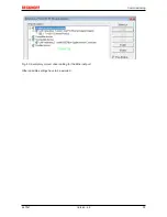
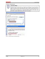
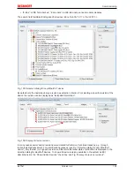
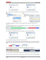
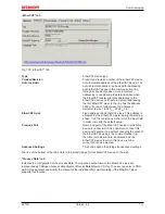
Fig. 112:
Note for automatic device scan (left: TwinCAT 2; right: TwinCAT 3)
Ethernet ports with installed TwinCAT real-time driver are shown as “RT Ethernet” devices. An EtherCAT
frame is sent to these ports for testing purposes. If the scan agent detects from the response that an
EtherCAT slave is connected, the port is immediately shown as an “EtherCAT Device” .
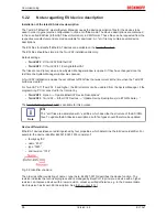
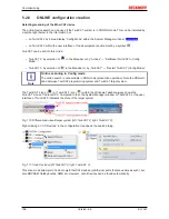
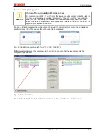
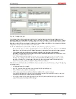
Fig. 113:
Detected Ethernet devices
Via respective checkboxes devices can be selected (as illustrated in Fig. “
Detected Ethernet devices
” e.g.
Device 3 and Device 4 were chosen). After confirmation with “OK” a device scan is suggested for all selected
devices, see Fig.: “
Scan query after automatic creation of an EtherCAT device”
.
Note
Selecting the Ethernet port
Ethernet ports can only be selected for EtherCAT devices for which the TwinCAT real-time
driver is installed. This has to be done separately for each port. Please refer to the respec-
tive
installation page [
}
92]
.
Detecting/Scanning the EtherCAT devices
Note
Online scan functionality
During a scan the master queries the identity information of the EtherCAT slaves from the
slave EEPROM. The name and revision are used for determining the type. The respective
devices are located in the stored ESI data and integrated in the configuration tree in the de-
fault state defined there.
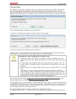
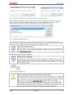
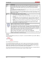
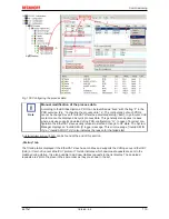
Fig. 114:
Example default state
Attention
Slave scanning in practice in series machine production
The scanning function should be used with care. It is a practical and fast tool for creating an
initial configuration as a basis for commissioning. In series machine production or reproduc-
tion of the plant, however, the function should no longer be used for the creation of the con-
figuration, but if necessary for
comparison [
}
113]
with the defined initial configura-
tion.Background: since Beckhoff occasionally increases the revision version of the deliv-
ered products for product maintenance reasons, a configuration can be created by such a
scan which (with an identical machine construction) is identical according to the device list;
however, the respective device revision may differ from the initial configuration.
Summary of Contents for EL7031
Page 1: ...Documentation EL70x1 Stepper Motor Terminals 4 4 2017 08 18 Version Date...
Page 2: ......
Page 6: ...Table of contents EL70x1 6 Version 4 4...
Page 48: ...Mounting and wiring EL70x1 48 Version 4 4 Fig 32 Other installation positions example 2...
Page 96: ...Commissioning EL70x1 96 Version 4 4 Fig 90 Incorrect driver settings for the Ethernet port...
Page 179: ...Commissioning EL70x1 179 Version 4 4 Index 7020 POS Outputs Ch 1...
Page 203: ...Commissioning EL70x1 203 Version 4 4 Index 7020 POS Outputs Ch 1...

