Mounting and wiring
EL922x
48
Version: 1.0
6.7.3
EL9227-xxxx
LEDs and connection
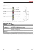
Fig. 33: EL9227-5500, assignment and designation of connections and LEDs
Meaning of the connections
Terminal point
Description
Name
No.
Digital input 1
1
Digital input for switching output 1
(negative edge; 0 V reference as supply)
24 V power supply
2
+24 V DC input voltage (internally connected to terminal point 6)
0 V power supply
3
0 V DC input voltage (internally connected to terminal point 7 and power contact 0 V)
Digital input 2
4
Digital input for switching output 2
(negative edge; 0 V reference as supply)
Protected output 1
5
Pro 24 V DC (internally connected to positive power contact)
Protected output 1
via power contact
Pro 24 V DC (internally connected to output 1)
24 V power supply
6
+24 V DC input voltage (internally connected to terminal point 2)
0 V power supply
7
0 V DC input voltage (internally connected to terminal point 3 and power contact 0 V)
Protected output 2
8
Pro 24 V DC,

