background image

Foreword

EP1918

7

Version: 1.1.0

1.2.3

Description of instructions

In these operating instructions the following instructions are used.
These instructions must be read carefully and followed without fail!

 DANGER

Serious risk of injury!

Failure

 to follow this safety instruction directly endangers the life and health of persons.

 WARNING

Risk of injury!

Failure

 to follow this safety instruction endangers the life and health of persons.

 CAUTION

Personal injuries!

Failure

 to follow this safety instruction can lead to injuries to persons.

NOTE

Damage to the environment/equipment or data loss

Failure

 to follow this instruction can lead to environmental damage, equipment damage or data loss.

Tip or pointer

This symbol indicates information that contributes to better understanding.

Summary of Contents for EP1918

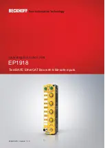
Page 1: ...Operating Instruction EN EP1918 TwinSAFE EtherCAT Box with 8 fail safe inputs 2020 09 10 Version 1 1 0 ...

Page 2: ......

Page 3: ...itions 16 4 2 Installation 16 4 2 1 Fixing 16 4 2 2 Connection 16 4 2 3 EP1918 temperature measurement 23 4 2 4 Signal cables 24 4 3 EP1918 configuration in TwinCAT 26 4 3 1 Adding an EtherCAT device 26 4 3 2 Inserting an EP1918 26 4 3 3 Using the integrated TwinSAFE Logic functions 26 4 3 4 Project design limits of the EP1918 27 4 3 5 Address settings on the TwinSAFE EtherCAT Box 28 4 3 6 Alias d...

Page 4: ... Version 1 1 0 4 6 Maintenance 46 4 7 Service life 46 4 8 Decommissioning 47 4 9 Firmware update of TwinSAFE products 48 5 Appendix 51 5 1 Protection classes according to IP code 51 5 2 Support and Service 52 5 3 Certificates 53 ...

Page 5: ...tion are valid Further information given on the product pages of the Beckhoff homepage in emails or in other publications is not authoritative Disclaimer The documentation has been prepared with care The products described are subject to cyclical revision For that reason the documentation is not in every case checked for consistency with performance data standards or other characteristics We reser...

Page 6: ...ion Modifications to hardware or software configurations other than those described in the documentation are not permitted and nullify the liability of Beckhoff Automation GmbH Co KG 1 2 2 Operator s obligation to exercise diligence The operator must ensure that the TwinSAFE products are only used as intended see chapter Product description the TwinSAFE products are only operated in sound conditio...

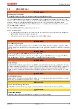
Page 7: ...dangers the life and health of persons WARNING Risk of injury Failure to follow this safety instruction endangers the life and health of persons CAUTION Personal injuries Failure to follow this safety instruction can lead to injuries to persons NOTE Damage to the environment equipment or data loss Failure to follow this instruction can lead to environmental damage equipment damage or data loss Tip...

Page 8: ...story lists the software and hardware version numbers A description of the changes compared to the previous version is also given Updated hardware and software TwinSAFE products are subject to a cyclical revision We reserve the right to revise and change the TwinSAFE products at any time and without prior notice No claims for changes to products already delivered can be asserted from these hardwar...

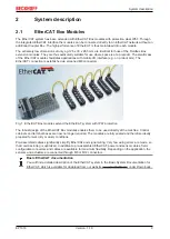
Page 9: ...ed M8 connectors Fig 1 EtherCAT Box modules extend the EtherCAT system with IP67 protection The robust design of the EtherCAT Box modules enables them to be used directly at the machine Control cabinets and terminal boxes are now no longer required The modules are fully sealed and therefore ideally prepared for wet dirty or dusty conditions Pre assembled cables significantly simplify EtherCAT and ...

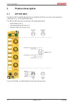
Page 10: ... is a digital EtherCAT Box for sensors with potential free contacts for 24 VDC It has eight fail safe inputs The EP1918 0002 meets the requirements of the following standards EN 61508 2010 SIL 3 EN 62061 2005 A2 2015 SIL CL 3 EN ISO 13849 1 2015 Cat 4 PL e Fig 2 EP1918 0002 TwinSAFE EtherCAT Box with 8 fail safe inputs ...

Page 11: ...he overall system must never lead to a dangerous condition The safe state is always the switched off and wat tless state WARNING Power supply from SELV PELV power supply unit The TwinSAFE components must be supplied with 24 VDC by an SELV PELV power supply unit with an out put voltage limit Umax of 36 VDC Failure to observe this can result in a loss of safety WARNING System limits The TÜV SÜD cert...

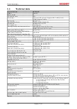
Page 12: ...ontacts 8 channels occupied approx 60 mA 0 channels occupied approx 35 mA provide 4 A fuse Power dissipation of the EtherCAT Box typically 3 8 watts Electrical isolation between the channels no Electrical isolation between the channels and EtherCAT yes Insulation voltage between the channels and Ether CAT under common operating conditions Insulation tested with 500 VDC Dimensions W x H x D 30 mm x...

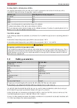
Page 13: ...emperature at which a switch off takes place This is designed for the maximum permissible ambient temperature If the derating factor for the temperature for higher altitudes is used the user is solely responsible for ensuring that the calculated maximum ambient temperature is complied with 3 4 Safety parameters Characteristic numbers EP1918 0002 Lifetime a 20 Proof test interval a not required1 PF...

Page 14: ...cable If clocked signals clock outputs for the safe inputs of different modules are used within a sheathed cable a fault of one module such as cross circuit or external feed must lead to the switch off of all of these mod ules This is achieved by setting the Module Fault Link active parameter for all modules involved This pa rameter is set to TRUE by default DANGER Safe inputs in Cat 4 PL e If two...

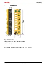
Page 15: ...ersion 1 1 0 3 6 Dimensions Fig 3 EP1918 0002 Dimensions The TwinSAFE EtherCAT Box has the following dimensions Width 30 0 mm Height 126 0 mm Depth 26 5 mm When fully wired the connected cables increase the total depth of the module ...

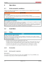
Page 16: ...he function of the TwinSAFE components may be impaired 4 2 Installation 4 2 1 Fixing NOTE Protect connectors against soiling Protect all connections from contamination during installation and operation of the modules Protection class IP67 is only guaranteed if all cables and plug connectors are connected and unused connections are protected with the appropriate cover plugs Connector sets see catal...

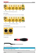
Page 17: ...rque of 0 6 Nm Fig 5 EtherCAT Box with M8 and M12 connectors 7 8 plug connectors We recommend fastening the 7 8 plug connectors with a torque of 1 5 Nm Fig 6 7 8 plug connectors Torque wrench Fig 7 Torque wrench ZB8801 NOTE Ensure the proper torque is used Use torque wrenches available from Beckhoff to tighten the connectors see accessories ...

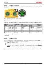
Page 18: ... Pin 2 white1 blue white2 white green Rx Receive Data Pin 3 blue1 blue2 green Shield Shield Housing Shield Shield Shield 1 Core colors according to EN 61918 2 Core colors 4 2 2 3 EtherCAT cables For connecting EtherCAT devices only Ethernet cables that meet the requirements of at least category 5 CAT5 according to EN 50173 or ISO IEC 11801 should be used Wiring recommendations Detailed recommendat...

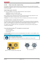
Page 19: ...be found later in this chapter General information for connecting the functional earth The earth connection of the EP1918 see figure EP1918 power connection and FE and the grounding sleeves in the fastening holes for the M3 screws for fixing the EtherCAT Box are internally connected The earth connection is capacitively connected to Us Up and the shield of the EtherCAT connection The earthing screw...

Page 20: ... the destruction of the modules Control voltage Us The fieldbus and the processor logic are supplied from the 24 VDC control voltage Us The control voltage is electrically isolated from the fieldbus circuitry Peripheral voltage Up The peripheral voltage Up supplies the digital clock outputs and the safe inputs Redirection of the supply voltages The power IN and OUT connections are bridged in the m...

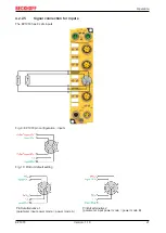
Page 21: ...gnal connection for inputs The EP1918 has 8 safe inputs Fig 9 EP1918 pin configuration inputs Fig 10 PinOut default setting PinOut alternative 1 parameter input power mode power mode A PinOut alternative 2 parameter input power mode power mode B ...

Page 22: ...4 VDC Sensor supply 4 Input 6 Input 6 Input 6 5 not connected not connected not connected 4 In 7 8 1 7 Pulse output 7 24 VDC Sensor supply 0 VDC Sensor supply 2 Input 7 Input 7 Input 7 3 8 Pulse output 8 0 VDC Sensor supply 24 VDC Sensor supply 4 Input 8 Input 8 Input 8 5 not connected not connected not connected NOTE Sensor supply For the sensor supply please ensure that the maximum current input...

Page 23: ...le EtherCAT Box that is wired with corresponding supply and communication cables The inputs and or outputs of the EtherCAT Box are switched on for the test NOTE External heat sources radiant heat impaired convection The maximum permissible ambient temperature of 60 C was checked with the example configuration de scribed above Impaired convection or an unfavorable location near heat sources may hav...

Page 24: ...e length When connecting a single switching contact via a dedicated continuous cable or via a sheathed cable the maximum permitted cable length is 100 m if a sensor test is active The use of contact points connectors or additional switching contacts in the cabling reduces the maximum propagation ...

Page 25: ...in parallel can influence the signal form of the test pulses and thus cause diagnostic messages e g sensor errors or OpenLoad errors D Distance between the cable ducts should be as large as possible blue arrows signal line red arrows potential source of interference The common routing of signals together with other clocked signals in a common cable also reduces the maximum propagation since crosst...

Page 26: ... the EP1918 Fig 14 Inserting an EP1918 4 3 3 Using the integrated TwinSAFE Logic functions On delivery the EP1918 behaves like a safe TwinSAFE I O slave which can be used as an alias device within a TwinSAFE Logic e g EL6910 Alternatively the local logic function of the EP1918 can be used To this end please create a TwinSAFE project in the Safety Editor and select the EP1918 as the target system F...

Page 27: ...s i e with the same size of input and output process data a maximum size of 1280 bytes per data direction results Only even numbered start addresses are possible therefore padding bytes may have to be included TwinSAFE connections maximum 212 Maximum 255 CRCs in total 1 CRC is required for a TwinSAFE connection with 1 or 2 bytes of safe data Safe data per TwinSAFE connection maximum 126 byte teleg...

Page 28: ... using the three rotary switches on the underside of the TwinSAFE EP Box TwinSAFE addresses between 1 and 4095 are available Rotary switch Address 1 bottom 2 center 3 top 0 0 1 1 0 0 2 2 0 0 3 3 0 0 F 15 0 1 0 16 0 1 1 17 0 F F 255 1 0 0 256 1 0 1 257 F F F 4095 WARNING TwinSAFE address Each TwinSAFE address must be unique within a network The address 0 is not a valid address ...

Page 29: ...iguration The connection and device specific parameters are set via the alias devices Fig 17 Starting the automatic import from the I O configuration If the automatic import is started from the I O configuration a selection dialog opens in which the individual terminals to be imported can be selected Fig 18 Selection from the I O tree The alias devices are created in the safety project when the di...

Page 30: ...Operation EP1918 30 Version 1 1 0 Fig 19 Creating alias devices by the user ...

Page 31: ...hysical device Manual manual linking e g to network variables Local signals are used in the local logic Physical device Link to the TwinSAFE component within the TwinCAT solution DIP switch DIP or rotary switch address read from the TwinSAFE component Input Full name In manual mode Display of the variables below the TwinSAFE Logic e g EL6910 Input Linked to In manual mode Display of the linked var...

Page 32: ...his connection This setting directly affects the fault response time Module Fault is ComError If the checkbox is checked module error also triggers a ComError which switches the TwinSAFE group where the connection was created to the error state Com ERR Ack For each connection an additional error acknowledge can be configured In this case the connection must also be acknowledged in addition to the ...

Page 33: ...ve must be FALSE Power mode B Diag TestPulse active must be FALSE see chapter Signal connection for inputs 21 8001 01 Channel1 InputFilterTime 0x000A 0 1 ms Input filter of the safe input Following this time the internal input sig nal changes to the applied signal state Internal test pulses can have a length of up to 2 ms 8001 02 Channel1 DiagTestPulseFilter Time 0x0002 0 1 ms Input filter for the...

Page 34: ...nel1 Input IN 0 3 Safe input channel 3 FSIN Module2 Channel2 Input IN 0 4 Safe input channel 4 FSIN Module2 Module Fault IN 0 5 Module error information for safe input module 2 FSIN Module3 Channel1 Input IN 0 6 Safe input channel 5 FSIN Module3 Channel2 Input IN 0 7 Safe input channel 6 FSIN Module3 Module Fault IN 1 0 Module error information for safe input module 3 FSIN Module4 Channel1 Input I...

Page 35: ...f the communication This is typically 3 times the EtherCAT cycle time since a new Safety over EtherCAT telegram has to be generated before new data can be sent These times depend directly on the higher level standard controller cycle time of the PLC NC RTLogic Response time of the logic terminal This is the cycle time of the logic terminal and typically ranges from 500 µs to 10 ms for the EL6900 d...

Page 36: ...ication interface This is detected by the logic once the watchdog time of the communication link has elapsed This information should then be passed on to the output resulting in a further communication error This fault is detected at the output once the watchdog time has elapsed resulting in shutdown This results in the following formula for the worst case response time max Comm Comm Actuator Reac...

Page 37: ...shes ACT communication with the preceding EtherCAT module OUT Link Act off no connection to the following EtherCAT module lit LINK connection to the following EtherCAT module flashes ACT Communication with the following EtherCAT module Run off Status of the EtherCAT module is Init flashes quickly Status of the EtherCAT module is pre operational flashes slowly Status of the EtherCAT module is safe ...

Page 38: ...t 4 is connected and logical 1 off Input 4 is not connected and logical 0 5 on Input 5 is connected and logical 1 off Input 5 is not connected and logical 0 6 on Input 6 is connected and logical 1 off Input 6 is not connected and logical 0 7 on Input 7 is connected and logical 1 off Input 7 is not connected and logical 0 8 on Input 8 is connected and logical 1 off Input 8 is not connected and logi...

Page 39: ...rred see diag history of the TwinSAFE components Dia3 red Global fault or global shutdown on µC11 No global fault or global shutdown on µC11 Dia4 red Global fault or global shutdown on µC21 No global fault or global shutdown on µC21 1 A global fault permanently disables the TwinSAFE component so that it has to be replaced A global shutdown temporarily disables the TwinSAFE component The error can ...

Page 40: ...ermanently set the TwinSAFE components to the Fail Stop state Index F984hex Device Info Data C1 CoE object F984hex currently displays internal temperature and voltage values for the TwinSAFE component Index Name Meaning Flags Default F984 01 Voltage C2 Voltage µC2 RO 0dec F984 02 Temperature C1 Temperature µC1 RO 0dec F984 03 Firmware CRC C1 CRC of the firmware on µC1 RO F984 04 Vendor data CRC C1...

Page 41: ...exchange or the process data lengths configured via the standard communication channel do not match the process data lengths calculated using the TwinSAFE logic program The START state is also assumed when a user is logged in for the purpose of deleting the current TwinSAFE logic program or transferring the user list In the START state no TwinSAFE groups and no TwinSAFE connections are processed 8...

Page 42: ... execution time of the TwinSAFE logic with a logic state of 1 Cycle time 1 25 value average value of 64 cycles RO 0hex FEA0 16 Min Safety Control Task Execution Time Minimum execution time of the TwinSAFE logic with a logic state of 1 Cycle time 1 25 value RO 0 hex FEA0 17 Max Safety Control Task Execution Time Maximum execution time of the TwinSAFE logic with a logic state of 1 Cycle time 1 25 va...

Page 43: ...layed in the TwinCAT logger window Overwrite Acknowledge Mode This setting is currently not supported 4 5 8 Diagnosis History The diagnostic history of the TwinSAFE devices that support this function is implemented in accordance with the ETG guideline ETG 1020 Chapter 13 Diagnosis Handling The diagnostic messages are saved by the TwinSAFE device in a dedicated CoE object under 0x10F3 and can be re...

Page 44: ... 0 10F3 45 Diagnosis Message 064 Diagnosis message 64 BYTE 32 RO 0 Structure of the diagnosis messages DiagCode 4 bytes in this case always 0x 0000 E000 Flags 2 bytes diagnosis type info warning or error time stamp and number of parameters contained see the following table Text ID 2 bytes ID of the diagnosis message as a reference to the message text from the ESI XML Time stamp 8 bytes local slave...

Page 45: ...E device On the basis of the Text ID contained in the diagnostic message the corresponding plain text message can be found in the respective languages The parameters can be inserted in the appropriate positions In the following example x is used for a hexadecimal representation of the parameters Fig 32 ESI XML message text Via the entry New Messages Available the user receives information that new...

Page 46: ...o longer be operated WARNING Have soiled terminals checked Cleaning of the TwinSAFE component by the user is not permitted Please send soiled terminals to the manufacturer for inspection and cleaning 4 7 Service life The TwinSAFE EtherCAT Boxes have a service life of 20 years Due to the high diagnostic coverage within the lifecycle no special proof tests are required Date code The TwinSAFE EtherCA...

Page 47: ... disassembly of the EtherCAT Boxes Disposal The device must be removed for disposal Housing parts WELLAMID can be sent for plastic recycling Sealing compound Polyurethane resin Metal parts can be sent for metal recycling Electronic parts such as disk drives and circuit boards must be disposed of in accordance with national electronics scrap regulations ...

Page 48: ...ate It is necessary that you have control over the machine i e you can see it and thus ensure that it is in a safe state and that a firmware update can be carried out without endangering the operators or other personnel NOTE Avoid communication interruptions during the download Please avoid disconnecting the EtherCAT connection while downloading the firmware under any circum stances If a communica...

Page 49: ... No Nein 4 The system is now in Configuration mode Fig 35 Firmware update of TwinSAFE products Part 1 To perform the firmware update select the Online tab 6 for the EtherCAT Device 5 If you want to update several components you can select the corresponding components 7 together for individual components select only these Subsequently click with the right mouse button inside the selected area and s...

Page 50: ... select the firmware file 9 and click Open 10 Confirm the window that then opens with OK 11 the firmware update is then performed After successful completion you must click OK 12 in the concluding Function Succeeded window You can then switch the system back to Run mode and use the TwinSAFE system Fig 37 Firmware update of TwinSAFE products Part 3 ...

Page 51: ...parts with a wire Protection against ingress of dust Ingress of dust is not prevented completely although the quantity of dust able to penetrate is limited to such an extent that the proper function of the device and safety are not impaired 6 Protection against access to hazardous parts with a wire Dust proof No ingress of dust 2nd digit Protection against ingress of water 2nd digit Meaning 0 Non ...

Page 52: ...ff components there Beckhoff Headquarters Beckhoff Automation GmbH Co KG Huelshorstweg 20 33415 Verl Germany Phone 49 5246 963 0 Fax 49 5246 963 198 e mail info beckhoff com Beckhoff Support Support offers you comprehensive technical assistance helping you not only with the application of individual Beckhoff products but also with other wide ranging services support design programming and commissi...

Page 53: ...Appendix EP1918 53 Version 1 1 0 5 3 Certificates ...

Page 54: ... switches on the underside 28 Fig 17 Starting the automatic import from the I O configuration 29 Fig 18 Selection from the I O tree 29 Fig 19 Creating alias devices by the user 30 Fig 20 Linking tab of the EP1918 31 Fig 21 Connection tab of the EP1918 32 Fig 22 EP1918 Parameters 33 Fig 23 Process image of the EP1918 34 Fig 24 Typical response time 35 Fig 25 Worst case response time 36 Fig 26 Ether...

Page 55: ......
Page 56: ...Beckhoff Automation GmbH Co KG Hülshorstweg 20 33415 Verl Germany Phone 49 5246 9630 info beckhoff com www beckhoff com More Information www beckhoff com EP1918 ...

Reviews: