background image

Mounting and wiring

KL2542

16

Version: 2.0.0

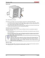
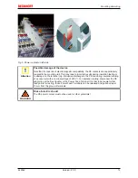
Terminals for standard wiring ELxxxx/KLxxxx and for pluggable wiring ESxxxx/KSxxxx

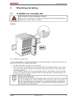
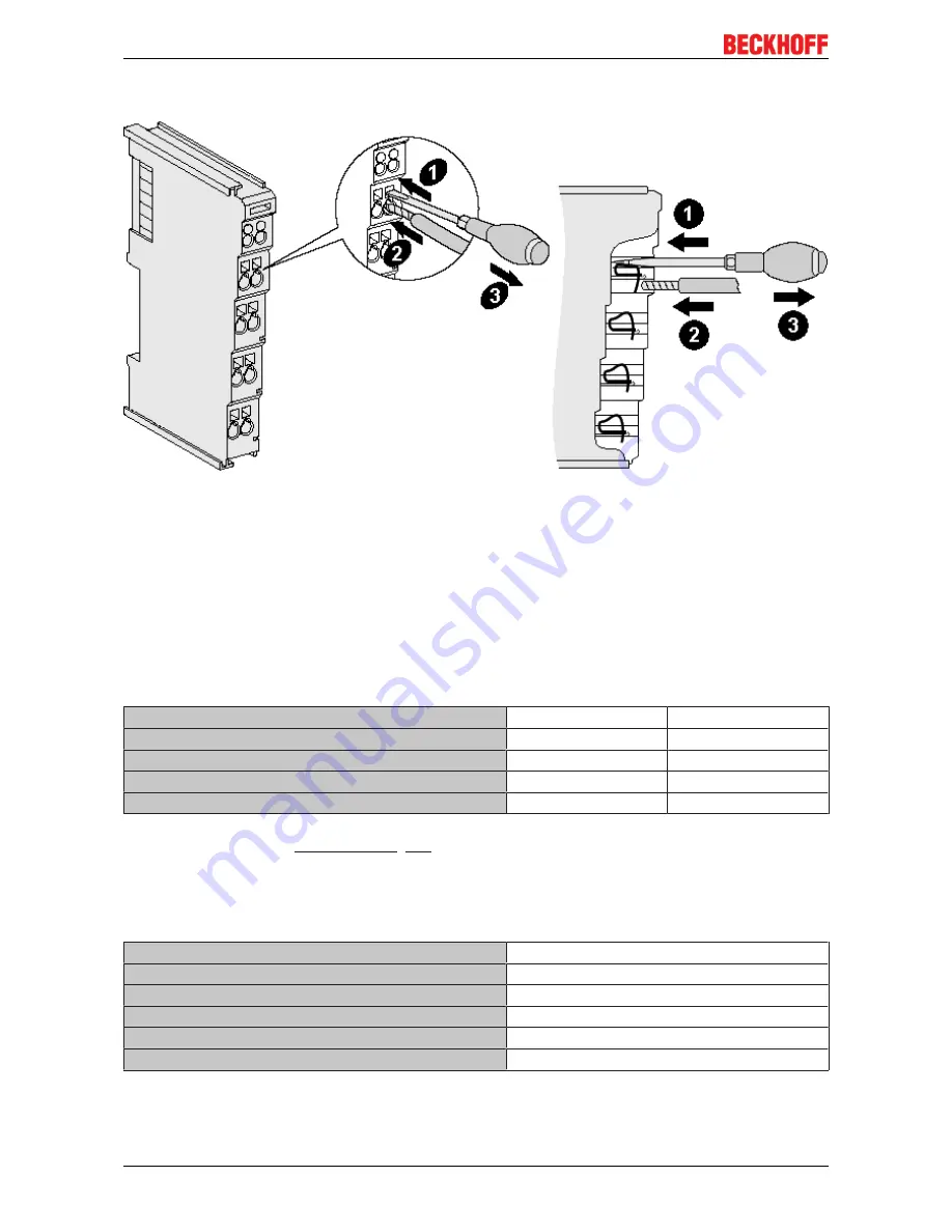
Fig. 9: Connecting a cable on a terminal point

Up to eight terminal points enable the connection of solid or finely stranded cables to the Bus Terminal. The
terminal points are implemented in spring force technology. Connect the cables as follows:

1. Open a terminal point by pushing a screwdriver straight against the stop into the square opening

above the terminal point. Do not turn the screwdriver or move it alternately (don't toggle).

2. The wire can now be inserted into the round terminal opening without any force.

3. The terminal point closes automatically when the pressure is released, holding the wire securely and

permanently.

See the following table for the suitable wire size width.

Terminal housing

ELxxxx, KLxxxx

ESxxxx, KSxxxx

Wire size width (single core wires)

0.08 ... 2.5 mm

2

0.08 ... 2.5 mm

2

Wire size width (fine-wire conductors)

0.08 ... 2.5 mm

2

0,08 ... 2.5 mm

2

Wire size width (conductors with a wire end sleeve)

0.14 ... 1.5 mm

2

0.14 ... 1.5 mm

2

Wire stripping length

8 ... 9 mm

9 ... 10 mm

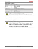
High Density Terminals (

HD Terminals [

}

 15]

) with 16 terminal points

The conductors of the HD Terminals are connected without tools for single-wire conductors using the direct
plug-in technique, i.e. after stripping the wire is simply plugged into the terminal point. The cables are
released, as usual, using the contact release with the aid of a screwdriver. See the following table for the
suitable wire size width.

Terminal housing

High Density Housing

Wire size width (single core wires)

0.08 ... 1.5 mm

2

Wire size width (fine-wire conductors)

0.25 ... 1.5 mm

2

Wire size width (conductors with a wire end sleeve)

0.14 ... 0.75 mm

2

Wire size width (ultrasonically “bonded" conductors)

only 1.5 mm

2

Wire stripping length

8 ... 9 mm

Summary of Contents for KL2542

Page 1: ...Documentation KL2542 Two channel output stage terminal for DC motors 2 0 0 2017 08 02 Version Date...

Page 2: ......

Page 3: ...on system 14 3 2 2 Wiring 15 3 2 3 Connection 17 4 KS2000 Configuration Software 19 4 1 KS2000 Introduction 19 4 2 Parameterization with KS2000 20 4 3 Settings 22 4 4 Register 25 4 5 Process data 26 5...

Page 4: ...Table of contents KL2542 4 Version 2 0 0...

Page 5: ...e data diagrams and descriptions in this documentation Trademarks Beckhoff TwinCAT EtherCAT Safety over EtherCAT TwinSAFE XFC and XTS are registered trademarks of and licensed by Beckhoff Automation G...

Page 6: ...iliar with the applicable national standards Description of symbols In this documentation the following symbols are used with an accompanying safety instruction or note The safety instructions must be...

Page 7: ...added 0 1 First provisional documentation for KL2542 Firmware and hardware versions Documentation Version Firmware Hardware 2 0 0 3A 10 1 0 0 1C 05 0 5 1C 05 0 4 1B 03 0 3 1B 03 0 2 1A 01 0 1 1A 01 Th...

Page 8: ...o DC motors The set speed or the position is specified by the automation device through a 16 bit value The output stage is protected against overload and short circuit and is electrically isolated fro...

Page 9: ...der system Encoder voltage 0 3 V 1 5 V Encoder voltage 1 2 5 V 24 V Encoder frequency max 250 kHz Electrical isolation 500 V K bus mains voltage Power supply for the electronics via the K bus Current...

Page 10: ...There is a signal at input 2 Right LED prism LED Display reserved Enable A green off Channel 1 is either not enabled or not ready to operate on Channel 1 is enabled and is ready to operate reserved E...

Page 11: ...ieldbus Coupler Join the compo nents with tongue and groove and push the terminals against the mounting rail until the lock clicks onto the mounting rail If the Terminals are clipped onto the mounting...

Page 12: ...s The six spring contacts of the K Bus E Bus deal with the transfer of the data and the supply of the Bus Terminal electronics The power contacts deal with the supply for the field electronics and thu...

Page 13: ...testing or to damage on the terminal e g disruptive discharge to the PE line during insulation testing of a consumer with a nominal voltage of 230 V For insulation testing disconnect the PE supply li...

Page 14: ...Standard wiring ELxxxx KLxxxx Fig 6 Standard wiring The terminals of ELxxxx and KLxxxx series have been tried and tested for years They feature integrated screwless spring force technology for fast an...

Page 15: ...s the packaging density is twice as large as that of the standard 12 mm Bus Terminals Massive conductors and conductors with a wire end sleeve can be inserted directly into the spring loaded terminal...

Page 16: ...wire size width Terminal housing ELxxxx KLxxxx ESxxxx KSxxxx Wire size width single core wires 0 08 2 5 mm2 0 08 2 5 mm2 Wire size width fine wire conductors 0 08 2 5 mm2 0 08 2 5 mm2 Wire size width...

Page 17: ...Encoder B connection A Encoder power 24 V 3 Encoder supply from positive power contact Input 1 4 Digital input 1 24 VDC The current counter value is saved as a reference mark in the latch register if...

Page 18: ...ion Power contacts The voltage Up of the power contacts 24 VDC supplies the following consumers Incremental encoder terminal points 3 and 7 Digital inputs terminal points 4 and 8 Output driver of the...

Page 19: ...s Box Modules can be prepared before the commissioning phase Later on this configuration can be transferred to the terminal station in the commissioning phase by means of a download For documentation...

Page 20: ...t and output images can be observed by monitoring Process values can be specified in the output image for commissioning of the output modules All possibilities in the online mode can be used in parall...

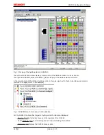
Page 21: ...station terminals In the tree structure of the left hand window click on the plus sign next to the terminal whose parameters you wish to change item 2 in the example Fig 13 KS2000 branch for channel...

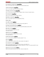
Page 22: ...ntroller for 100 ms when the watchdog is active the watchdog is triggered and the motor stops Signed amount representation R32 3 35 Here you can activate the signed amount representation default inact...

Page 23: ...0 Switching threshold for MixedDecay R41 36 Here you can specify the automatic switch off threshold for MixedDecay default 20 Rated motor current R37 36 Here you can specify the rated motor current T...

Page 24: ...r the application default 10000 see description of register R2 33 If the current value register R2 exceeds this threshold only a warning is issued if torque monitoring 33 is disabled SB1 5 29 1 and R0...

Page 25: ...ion Software KL2542 25 Version 2 0 0 4 4 Register You can access the registers of the KL2542 directly under Register The meaning of the register is explained in the register overview 31 Fig 15 Registe...

Page 26: ...splayed in a tree structure under ProcData Fig 16 ProcData The reading glasses mark the data that are currently graphically displayed in the History field Fig 17 History field The current input values...

Page 27: ...s forcing them can have a direct effect on your automation application Only modify these initial values if you are certain that the state of your equip ment permits it and that there will be no risk t...

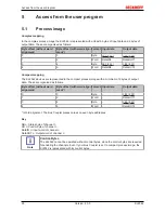
Page 28: ...ed in the compact process image with a minimum of 6 bytes of output data These are organized as follows Byte offset without word alignment Byte offset with word align ment Format Input data Output dat...

Page 29: ...e input process data CB1 3 enLatch FallEdge 1bin External latch event is enabled for latch inputs with falling edge the terminal saves the current position CB1 2 enLatch RiseEdge 1bin External latch e...

Page 30: ...t for GetLatchData SB1 2 LatchValid 1bin A latch event has occurred with CB1 2 1 or CB1 3 1 SB1 1 SetPos Ready 1bin The current position has been set acknowledgement for SetPos SB1 0 Input E1 Status o...

Page 31: ...ult value R W Memory R0 33 Status word 0x0000 0dec R RAM R1 33 Set position 0x0000 0dec R W RAM R2 33 Torque e g 0x015E e g 350dec R RAM R3 34 Supply voltage e g 0x0030 e g 48dec R RAM R4 reserved R5...

Page 32: ...only 0x0000 0dec R W EEPROM R40 36 Internal resistance of the motor 0x0064 100dec R W EEPROM R41 36 Automatic switch off threshold for MixedDecay 0x0014 20dec R W EEPROM R42 36 Kp factor 0x1000 4096d...

Page 33: ...driver stage R0 11 Under Voltage 1bin Supply voltage less than 7 V R0 10 Over Voltage 1bin Supply voltage greater than 15 of the switch on voltage with R39 0 or greater than specified in R39 with R39...

Page 34: ...R40 36 100dec R41 36 20dec R42 36 4096dec R43 36 1dec R44 37 5dec R45 37 100dec R46 37 500dec R47 37 10000dec Note Restore Factory Settings The command Restore Factory Settings simultaneously resets b...

Page 35: ...ee R42 36 0bin R32 14 disIPart 1bin I component of the velocity control is deactivated see R44 37 R45 37 0bin R32 13 disIWindow 1bin Inner window of the I component is deactivated see R43 36 0bin R32...

Page 36: ...9 35 1 the motor is de energized and an error is issued SB1 6 29 1 and R0 13 33 1 R39 Chopper voltage channel 2 only If the supply voltage increases above the set chopper voltage due to feedback the...

Page 37: ...mple 500 0 5 s The saved torque is then deleted and overwritten with the next larger value If torque cutoff is active the motor is de energized if the current torque for this time is greater than the...

Page 38: ...eturns the firmware version 0x3341 in the input data word byte 1 and byte 2 This is to be interpreted as an ASCII code ASCII code 0x33 represents the digit 3 ASCII code 0x41 represents the letter A Th...

Page 39: ...Byte 1 DataIN1 high byte Byte 2 DataIN1 low byte 0x9F 1001 1111bin 0x12 0x35 Explanation The terminal returns the value of the control byte as a receipt in the status byte The terminal returns the cu...

Page 40: ...yte 0 Status byte Byte 1 DataIN1 high byte Byte 2 DataIN1 low byte 0xA0 1010 0000bin 0x00 0x02 Explanation The terminal returns the value of the control byte as a receipt in the status byte The termin...

Page 41: ...components there Beckhoff Headquarters Beckhoff Automation GmbH Co KG Huelshorstweg 20 33415 Verl Germany Phone 49 0 5246 963 0 Fax 49 0 5246 963 198 e mail info beckhoff com Beckhoff Support Support...

Page 42: ...Pluggable wiring 14 Fig 8 High Density Terminals 15 Fig 9 Connecting a cable on a terminal point 16 Fig 10 KL2542 connection 17 Fig 11 KS2000 configuration software 19 Fig 12 Display of the fieldbus s...

Reviews: