Access from the user program
KL2542
28
Version: 2.0.0
5
Access from the user program
5.1
Process image
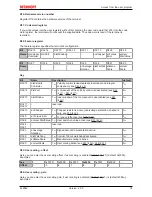
Complex mapping
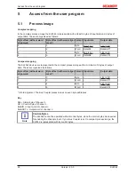
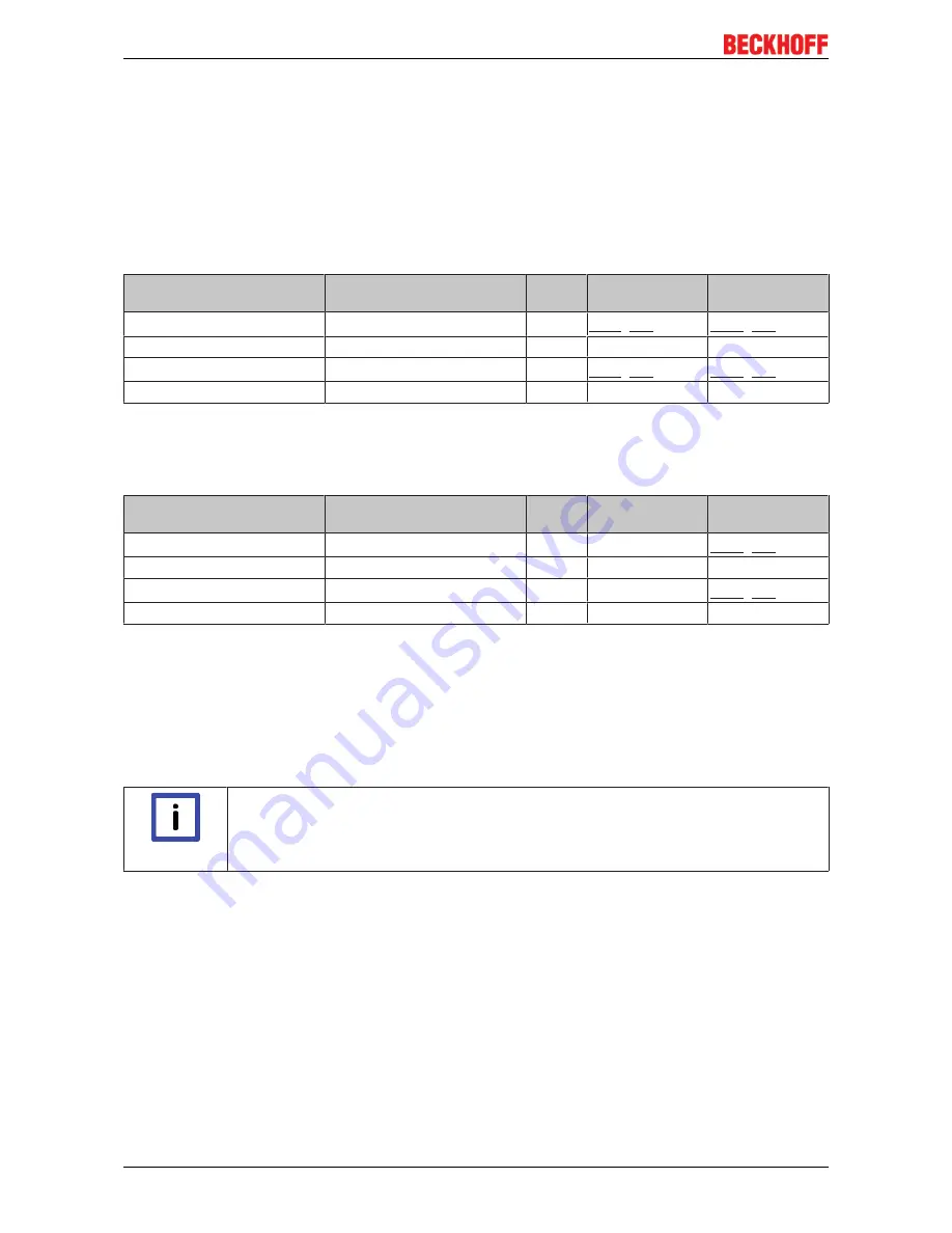
In the complex process image the KL2542 is represented with at least 6 bytes of input data and 6 bytes of
output data. These are organized as follows:
Byte offset (without word
alignment)
Byte offset (with word align-
ment*)
Format Input data
Output data
0
0
Byte
SB1 [
}
29]
:
CB1 [
}
29]
1
2
Word
DataIN1
DataOUT1
3
4
Byte
SB2 [
}
31]
CB2 [
}
31]
4
6
Word
DataIN2
DataOUT2
Compact mapping
The KL2542 devices are represented in the compact process image with a minimum of 6 bytes of output
data. These are organized as follows:
Byte offset (without word
alignment)
Byte offset (with word align-
ment*)
Format Input data
Output data
0
0
Byte
-
CB1 [
}
29]
1
2
Word
-
DataOUT1
3
4
Byte
-
CB2 [
}
31]
4
6
Word
-
DataOUT2
*) Word alignment: The Bus Coupler places values on even byte addresses
Key
SB n: Status byte of channel n
CB n: Control byte of channel n
DataIN n: Input word of channel n
DataOUT n: Output word of channel n
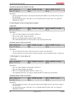
Note
Control-Bytes
The KL2542 cannot be operated without control bytes, since the control bytes are required
for enabling the channels. Even if your Bus Coupler is set to compact process image, the
KL2542 is represented with its control bytes.
Summary of Contents for KL2542
Page 2: ......

