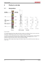
Product overview
KL3222
11
Version: 2.3.0
2.2
Technical data
Technical data
KL3222, KS3222
Inputs
2
Sensor types
PT100, PT200, PT500, PT1000, Ni100, Ni120, Ni1000,
resistance measurement (e.g. potentiometer connection, 10
Ω...1,2/5 kΩ), KTY
Connection technology
4-wire (2/3-wire possible, see below)
Measuring range
Pt sensors
-200…+850 °C
Ni sensors
-60…+250 °C
high-precision
-200…+320 °C
Conversion time
approx. 50 ms
Measuring current
typically 0.5 mA
Resolution
0.01°C per digit
Measuring accuracy
0.1 °C at 40 °C ambient temperature, 4-wire connection,
PT100 sensors and 50 Hz filter
Bit width in the input process image
2 data words, 2 status bytes (optional)
Bit width in the output process image
2 control bytes (optional)
Power supply for the electronics
via the K-bus
Current consumption from K-bus
typically 60 mA
Electrical isolation
500 V (K-Bus/signal voltage)
Terminal points
Spring-loaded terminals
for all KSxxxx terminals
Weight
approx. 70 g
Dimensions (W x H x D)
approx. 15 mm x 100 mm x 70 mm (width aligned: 12 mm)
on 35 mm mounting rail conforms to EN 60715
Permissible ambient temperature range during
operation
0 °C ... + 55 °C
Permissible ambient temperature range during
storage
-25 °C ... + 85 °C
Permissible relative air humidity
95 %, no condensation
Vibration / shock resistance
conforms to EN 60068-2-6/EN 60068-2-27, see also
for terminals with enhanced
mechanical load capacity
EMC immunity/emission
conforms to EN 61000-6-2 / EN 61000-6-4
Protection class
IP20
Installation position
variable
Approval
CE, cULus,
The KL3222 is designed for 4-wire measurement
The KL3222 is designed for 4-wire measurement. +R/-R are the current-carrying connection cables,
+RL/-RL are the currentless sense cables.
If a sensor is to be connected using 2/3 wire connection technology and the KL3202 cannot be
used, the following applies
• one or two jumper(s) per channel must be set externally, see wiring diagram
• the setting "four-wire" must be retained in R32, the 2/3-wire measurement is not calibrated by the
manufacturer
• the falsifying lead resistance should be entered in R38. The firmware subtracts this lead resis-
tance from the measured resistance in order to determine a corrected temperature. This calcula-
tion of R38 is active in all 3 modes 2/3/4-wire of R32.
Summary of Contents for KL3222
Page 2: ......

