Access from the user program
KL3222
38
Version: 2.3.0
•
R33: User scaling - offset
This register contains the offset of the user scaling. User scaling can be enabled in the feature register
via bit
•
R34: user scaling - gain
This register contains the gain of the user scaling. User scaling can be enabled in the feature register
via bit
•
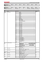
R37: filter constant of the A/D converter
Value in R37
Limit frequency
Default
0
dec
50 Hz
0
dec
1
dec
60 Hz
2
dec
100 Hz
3
dec
500 Hz
4
dec
1000 Hz
5
dec
2000 Hz
6
dec
3750 Hz
7
dec
7500 Hz
8
dec
15 kHz
9
dec
30 kHz
10
dec
5 Hz
11
dec
10 Hz
5.5
Examples of Register Communication
The numbering of the bytes in the examples corresponds to the display without word alignment.
5.5.1
Example 1: reading the firmware version from Register 9
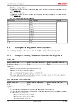
Output Data
Byte 0: Control byte
Byte 1: DataOUT1, high byte
Byte 2: DataOUT1, low byte
0x89 (1000 1001
bin
)
0xXX
0xXX
Explanation:
• Bit 0.7 set means: Register communication switched on.
• Bit 0.6 not set means: reading the register.
• Bits 0.5 to 0.0 specify the register number 9 with 00 1001
bin
.
• The output data word (byte 1 and byte 2) has no meaning during read access. To change a register,
write the required value into the output word.
Input Data (answer of the bus terminal)
Byte 0: Status byte
Byte 1: DataIN1, high byte
Byte 2: DataIN1, low byte
0x89
0x33
0x41
Explanation:
• The terminal returns the value of the control byte as a receipt in the status byte.
• The terminal returns the firmware version 0x3341 in the input data word (byte 1 and byte 2). This is to
be interpreted as an ASCII code:
◦ ASCII code 0x33 represents the digit 3
◦ ASCII code 0x41 represents the letter A
The firmware version is thus 3A.
Summary of Contents for KL3222
Page 2: ......


