Mounting and wiring
KL3403
35
Version: 3.1.0
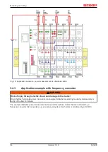
Fig. 20: Application example with frequency converter
The electrical isolation of the three-phase-transformer (Yy0) operated by the voltage circuit of the power
measurement terminals enables measurement after the frequency converter.
Measuring error in the lower frequency range
If the power measurement takes place after the frequency converter, a larger measuring error is
possible in the lower frequency range, particularly for voltage measurement. This error also affects
the power calculation.
The three-phase transformer should have a ratio of 1:1. It must not cause a phase shift of the signal! Since
high-frequency components only have little influence on the motors, any distortions caused by the three-
phase transformer have little effect on the practical measurement during the transfer of the harmonics
created by the frequency converter.
The power distribution is mapped very well by using a dedicated power measurement terminal for each
motor. Excessive current consumption of an individual motor can be detected in good time.
It is not possible to use this method for measuring direct voltage/DC (e.g. holding currents of synchronous
motors)! Practical results can be obtained for voltages/currents with a frequency above 5 Hz, depending on
the three-phase transformer and current transformers used.
CAUTION
The terminal points N must be grounded!
Due to the electrical isolation through the three-phase transformer, the terminal points N of the power mea-
surement terminals have to be grounded, in order to avoid dangerous overvoltages in the event of a fault in
a current transformer!


