Product overview
KL403x
12
Version: 4.1
2.3
Basic function principles
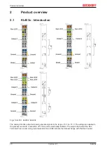
The KL403x analog output terminals generate signals in the range -10 V to +10 V with a resolution of 12 bits
(4095 steps). The output voltage is electrically isolated from the K-Bus.
The LEDs indicate the operating state of the associated terminal channels.
• green Run LED:
◦ On: Normal operation
◦ Off: Watchdog timer overflow has occurred. If no process data are transmitted by the Bus Coupler
for 100 ms, the green LEDs go out. The output assumes a user-specified voltage (see
).
Process data input format
In the delivery state the process data are shown in two's complement form (integer -1 corresponds to
0xFFFF). Alternative presentation types can be selected via the feature register (
Output value
Process data
dec
hex
-10 V
(-32767)
0x8001
-5 V
(-16383)
0xC001
0 V
(0)
0x0000
5 V
(16383)
0x3FFF
10 V
(32767)
0x7FFF
Process data
The process data arriving from the Bus Coupler are output to the process:
Y_dac = X
(1.0)
Neither user nor manufacturer scaling is active.
Y_1 = B_h + A_h * X
Y_dac = Y_1
(1.1)
Manufacturer scaling active
Y_2 = B_w + A_w * X
Y_dac = Y_2
(1.2)
User scaling active
Y_1 = B_h + A_h * X
Y_dac = B_w + A_w * Y_1
(1.3)
(1.4)
Manufacturer and user scaling active
Key
Name
Name
Register
X
PLC process data
-
B_h
Manufacturer scaling: Offset
A_h
Manufacturer scaling: Gain
B_w
User scaling: Offset
A_w
User scaling: Gain
Y_dac
Output value for the D/A converter
-
The equations of the straight line are enabled via register
.
Summary of Contents for KL403 Series
Page 2: ......

