Access from the user program
KL6224
41
Version: 2.0.0
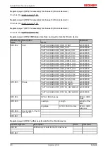
Value
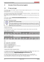
Process image
Default
0002
hex
(6 bytes parameter interface and 6 bytes IO-Link process
data)
0004
hex
0004
hex
0005
hex
0006
hex
further
reserved
After changing the process image the Bus Coupler must be restarted for the modified process image to take
effect.
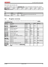
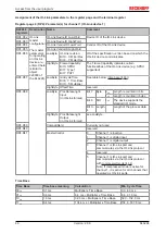
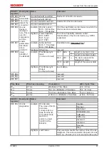
Register pages 4 to 9
Register pages for IO-Link parameters [
.
5.5
Examples of Register Communication
The numbering of the bytes in the examples corresponds to the display without word alignment.
5.5.1
Example 1: reading the firmware version from Register 9 of a
terminal
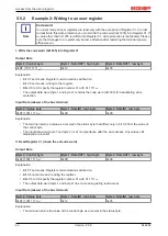
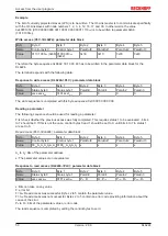
Output Data
Byte 0: Control byte
Byte 1: DataOUT1, high byte
Byte 2: DataOUT1, low byte
0x89 (1000 1001
bin
)
0xXX
0xXX
Explanation:
• Bit 0.7 set means: Register communication switched on.
• Bit 0.6 not set means: reading the register.
• Bits 0.5 to 0.0 specify the register number 9 with 00 1001
bin
.
• The output data word (byte 1 and byte 2) has no meaning during read access. To change a register,
write the required value into the output word.
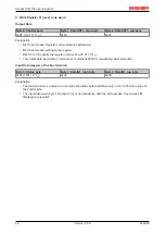
Input Data (answer of the bus terminal)
Byte 0: Status byte
Byte 1: DataIN1, high byte
Byte 2: DataIN1, low byte
0x89
0x33
0x41
Explanation:
• The terminal returns the value of the control byte as a receipt in the status byte.
• The terminal returns the firmware version 0x3341 in the input data word (byte 1 and byte 2). This is to
be interpreted as an ASCII code:
◦ ASCII code 0x33 represents the digit 3
◦ ASCII code 0x41 represents the letter A
The firmware version is thus 3A.


