background image

Access from the user program

KL6224

52

Version: 2.0.0

5.8

Firmware version of the Bus Couplers

Note

Required firmware

A particular firmware version may be required for operating the KL6224 IO-Link terminal on
the Bus Coupler / Bus Terminals Controller (see 

table [

}

 53]

 below)

In delivery state the KL6224 is set to a process image of 24 bytes.

Most Bus Couplers and Bus Terminal Controllers listed in the table support the 12-byte process image.
Bus Couplers / Bus Terminals Controllers that are not listed are not yet ready for operation with 24-byte
process images or higher.

The delivered firmware version is shown on the back of the Bus Coupler (see example below for CANopen).

Fig. 30: Specification of the firmware version on a Bus Coupler

If required, the firmware can be updated via the serial port (KS2000 cable required) or - depending on the
bus system - via the fieldbus. The current firmware versions and the program for the firmware update can be
found on our home page at 

http://www.beckhoff.de

.

Summary of Contents for KL6224

Page 1: ...Documentation KL6224 IO Link Terminal 2 0 0 2017 05 17 Version Date...

Page 2: ......

Page 3: ...9 3 5 LED display 20 4 KS2000 Configuration Software 21 4 1 KS2000 Introduction 21 4 2 Configuration of the KL6224 23 4 3 Register 25 4 4 Settings 26 5 Access from the user program 34 5 1 Process imag...

Page 4: ...Table of contents KL6224 4 Version 2 0 0...

Page 5: ...e data diagrams and descriptions in this documentation Trademarks Beckhoff TwinCAT EtherCAT Safety over EtherCAT TwinSAFE XFC and XTS are registered trademarks of and licensed by Beckhoff Automation G...

Page 6: ...iliar with the applicable national standards Description of symbols In this documentation the following symbols are used with an accompanying safety instruction or note The safety instructions must be...

Page 7: ...Hardware 1 0 0 03 02 0 5 00 01 The firmware and hardware versions delivery state can be taken from the serial number printed on the side of the terminal The KL6224 supports the IO Link specification...

Page 8: ...arameterization information can be exchanged bidirectionally via the IO Link connection The IO Link devices can be parameterized via the KS2000 configuration software or from the PLC via register comm...

Page 9: ...20 Electrical isolation 500 V IO Link K bus Weight app 60 g K bus bit width depends on the process image Configuration via fieldbus parameter interface DP V1 or Bus Coupler via Configuration software...

Page 10: ...new designation SDCI will be introduced at the same time As a member of the respective committee Beckhoff supports the development of IO Link and reflects changes to the specification in its products...

Page 11: ...ranges are available Index range Name 0x00 0x0F System 0x10 0x1F Identification 0x20 0x2F Diagnostic 0x30 0x3F Communication 0x40 0xFE Preferred Index 0x0100 0x3FFF Extended Index 0x4000 0xFFFF not s...

Page 12: ...ieldbus Coupler Join the compo nents with tongue and groove and push the terminals against the mounting rail until the lock clicks onto the mounting rail If the Terminals are clipped onto the mounting...

Page 13: ...s The six spring contacts of the K Bus E Bus deal with the transfer of the data and the supply of the Bus Terminal electronics The power contacts deal with the supply for the field electronics and thu...

Page 14: ...nts for testing these Power Feed Terminals can be released and pulled at least 10 mm from the group of terminals WARNING Risk of electric shock The PE power contact must not be used for other potentia...

Page 15: ...n the strain relief and the wire connection should be kept as short as possible A distance of approx 10 cm should be maintained to the cable duct 3 3 Connection system WARNING Risk of electric shock a...

Page 16: ...on wires when the connector is removed Conductor cross sections between 0 08 mm2 and 2 5 mm2 can continue to be used with the proven spring force technology The overview and nomenclature of the produc...

Page 17: ...ng the wire securely and per manently Terminal housing ELxxxx KLxxxx ESxxxx KSxxxx Wire size width 0 08 2 5 mm2 0 08 2 5 mm2 Wire stripping length 8 9 mm 9 10 mm High Density Terminals ELx8xx KLx8xx H...

Page 18: ...Mounting and wiring KL6224 18 Version 2 0 0 Shielding Note Shielding Analog sensors and actors should always be connected with shielded twisted paired wires...

Page 19: ...connection Connection Terminal point Description Name No Input 1 1 Input 1 24 V 2 24 V Input 2 3 Input 2 24 V 4 24 V Input 3 5 Input 3 24 V 6 24 V Input 4 7 Input 4 24 V 8 24 V 24 V 9 24 V 0 V 10 0 V...

Page 20: ...icate the terminal s operating state off no data transfer on the K bus flashes data transmission on the K bus State Ch 1 4 green on off Status of the signal line if configured as STD in out flashes br...

Page 21: ...s Box Modules can be prepared before the commissioning phase Later on this configuration can be transferred to the terminal station in the commissioning phase by means of a download For documentation...

Page 22: ...es directly online The same high level dialogs and register access are available for this purpose as in the configuration phase The KS2000 offers access to the process images of the bus couplers and F...

Page 23: ...connected fieldbus station In the example shown this is a BK9000 Ethernet Coupler a KL1xx2 Digital Input Terminal a KL6224 IO Link terminal a KL9010 bus end terminal Fig 13 Display of the fieldbus sta...

Page 24: ...l 1 of the KL6224 For the KL6224 the branches Register Settings and ProcData are displayed Register 25 permits direct access to the registers of the KL6224 Dialog boxes for the parameterization of the...

Page 25: ...ersion 2 0 0 4 3 Register You can access the registers of the KL6224 directly under Register The meaning of the register is explained in the register overview 39 Fig 15 Register view in KS2000 The scr...

Page 26: ...Communication channel The communication between KS2000 and the KL6224 can take place either via the fieldbus via ADS or via a serial cable via COM interface Click on Options Communication channel to s...

Page 27: ...vices button 2 Manual insertion 28 via catalog Catalog button 3 Import the device description 30 Import Device Description button Fig 19 Insert the IO Link devices Automatic scan of the IO Link ports...

Page 28: ...ication Mode For scanning the Communication mode must not be set to Communication Port1 Set tings Fig 21 Display of the detected IO Link devices The detected IO Link devices are displayed and the requ...

Page 29: ...Software KL6224 29 Version 2 0 0 Fig 22 Manual insertion via catalog Here you can Fig 23 Calling the create Device dialog use the create Device dialog to manually create an IO Link device Fig 24 The...

Page 30: ...Import the device description In the General dialog click on the Import Device Description button Fig 25 Import the device description The XML files for the IO Link devices are stored in the IO Link...

Page 31: ...in existing IODDs before scanning or manually inserting IO Link devices in or der to obtain further sensor specific information K bus interface Please note When changing IO Link devices the following...

Page 32: ...ndor ID and the device ID should be checked when the IO Link device starts up CycleTime Specifies the cycle time for the IO Link master Communication mode An IO Link device can be operated in differen...

Page 33: ...0 Data Storage is not supported V1 1 Data Storage is supported in delivery state default data sensor parameters are stored Process Data Format Here you can adjust the process data format If the check...

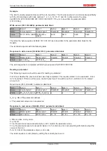
Page 34: ...d a 6 byte process data block Output data PLC KL6224 Parameter data block 6 bytes Process data block 6 bytes Byte 0 Byte 1 Byte 2 Byte 3 Byte 4 Byte 5 Byte 6 Byte 7 Byte 8 Byte 9 Byte 10 Byte 11 CB0 C...

Page 35: ...n Output data byte n DataIn n Input data byte n 14 byte process image The 14 byte process image consists of a 6 byte parameter data block and an 8 byte process data block Output data PLC KL6224 Param...

Page 36: ...Byte 6 Byte 7 Byte 8 Byte 9 Byte 10 Byte 11 CB0 CB1 ParaOut0 ParaOut 1 ParaOut 2 ParaOut3 DataOut0 DataOut1 DataOut2 DataOut3 DataOut4 DataOut25 Process data block 30 bytes continuation Byte 12 Byte...

Page 37: ...ta KL6224 PLC Parameter data block 6 bytes Process data block 42 bytes Byte 0 Byte 1 Byte 2 Byte 3 Byte 4 Byte 5 Byte 6 Byte 7 Byte 8 Byte 9 Byte 10 Byte 11 SB0 SB1 ParaIn0 ParaIn1 ParaIn2 ParaIn3 Sta...

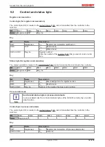
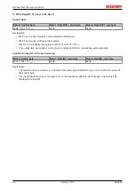
Page 38: ...located in the input image 34 and is transmitted from terminal to the controller Bit SB 7 SB 6 SB 5 SB 4 SB 3 SB 2 SB 1 SB 0 Name RegAccess R W Reg no Key Bit Name Description SB 7 RegAccess 1bin Ack...

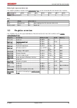
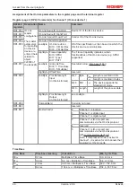
Page 39: ...egister Comment Default value R W Memory R0 to R3 reserved 0x0000 0dec R4 40 Register page 45 0x0004 4dec R W R5 to R7 reserved 0x0000 0dec R8 40 Terminal description 0x1850 6224dec R ROM R9 40 Firmwa...

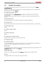
Page 40: ...irmware version Register R9 contains the firmware revision level of the terminal in hexadecimal coding e g 0x0100 256dec R10 Shift register length 0x0160 R11 Number of signal channels 0x0160 R12 Minim...

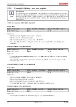
Page 41: ...rminal Output Data Byte 0 Control byte Byte 1 DataOUT1 high byte Byte 2 DataOUT1 low byte 0x89 1000 1001bin 0xXX 0xXX Explanation Bit 0 7 set means Register communication switched on Bit 0 6 not set m...

Page 42: ...code word 0x1235 for deactivating write protection Input Data answer of the bus terminal Byte 0 Status byte Byte 1 DataIN1 high byte Byte 2 DataIN1 low byte 0x9F 1001 1111bin 0xXX 0xXX Explanation The...

Page 43: ...before changing the values Input Data answer of the bus terminal Byte 0 Status byte Byte 1 DataIN1 high byte Byte 2 DataIN1 low byte 0xA0 1010 0000bin 0xXX 0xXX Explanation The terminal returns a valu...

Page 44: ...ecify the register number 31 with 01 1111bin The output data word byte 1 and byte 2 contains 0x0000 for reactivating write protection Input Data answer of the bus terminal Byte 0 Status byte Byte 1 Da...

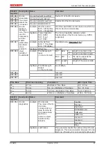
Page 45: ...ame meaning The contents of registers 32 to 63 are specified via the register page selection register R4 40 A register page has 32 registers 64 bytes The following register pages are used Register pag...

Page 46: ...t 6 7 Time Base Bit 0 5 Multiplier See table below time base 46 HighByte OffsetTime reserved RP4 R38 LowByte ProcDataLenght Input in IO Link format Bit 7 Byte 0bin Length is counted in bits 1bin Lengt...

Page 47: ...48 LowByte ProcDataLenght Input in IO Link format Bit 7 Byte 0bin Length is counted in bits 1bin Length is counted in bytes Bit 6 SIO 1bin The device supports the standard IO mode Bit 0 4 Length Lengt...

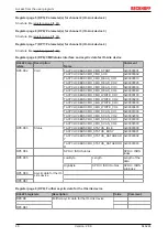
Page 48: ...CMD_CMD_READ_CH4 0x00000040 TACYCLICKBUSCMD_CMD_WRITE_CH1 0x00000100 TACYCLICKBUSCMD_CMD_WRITE_CH2 0x00000200 TACYCLICKBUSCMD_CMD_WRITE_CH3 0x00000300 TACYCLICKBUSCMD_CMD_WRITE_CH4 0x00000400 TACYCLIC...

Page 49: ...7 should be 0bin If this is not the case control bytes 0 and 1 should be set to 0 until bits 4 to 7 in status byte 1 are set to 0bin Write access PLC KL6224 parameter data block Byte Byte 0 Byte 1 By...

Page 50: ...0 00 00 00 00 00 Reading a parameter The following sequence should be used for reading a parameter First check whether the previous access was fully completed This requires status 1 to be evaluated bi...

Page 51: ...ntrol byte 1 ParaOut0 ParaOut1 ParaOut2 ParaOut3 Value 0011 0000bin 0x30 0100 0010bin 0x42 0x00 0x00 0x00 0x00 Therefore the byte sequence 0x30 42 00 00 00 00 has to be written in the parameter data b...

Page 52: ...the table support the 12 byte process image Bus Couplers Bus Terminals Controllers that are not listed are not yet ready for operation with 24 byte process images or higher The delivered firmware ver...

Page 53: ...0 from B3 in preparation in preparation CANopen BK5120 from C4 from C5 BK5150 all all BC5150 all all all BX5100 all all all DeviceNet BK5220 from B3 in preparation BC5250 all all all BX5200 all all al...

Page 54: ...components there Beckhoff Headquarters Beckhoff Automation GmbH Co KG Huelshorstweg 20 33415 Verl Germany Phone 49 0 5246 963 0 Fax 49 0 5246 963 198 e mail info beckhoff com Beckhoff Support Support...

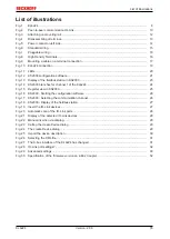
Page 55: ...for channel 1 of the KL6224 24 Fig 15 Register view in KS2000 25 Fig 16 KS2000 Starting the configuration software 26 Fig 17 KS2000 Selecting the communication channel 26 Fig 18 KS2000 Display of the...

Reviews: